• Steel Soldiers now has a few new forums, read more about it at: New Munitions Forums!

  • Microsoft MSN, Live, Hotmail, Outlook email users may not be receiving emails. We are working to resolve this issue. Please add support@steelsoldiers.com to your trusted contacts.

M920 Volt meter wiring

jamboly

Active member
205
7
28
Location
Brenham, TX
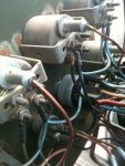
Got my 920 a couple of weeks ago. Working through problems one by one. I am now trying to determine why batteries (new) aren't charging. I started out by looking at the voltmeter gauge (on dash). I have attached a picture of the wiring as well as a partial diagram of the wiring to the voltmeter. The first thing I noticed was that the leads that should normally be attached to one of the meter terminals was attached to the bolt that is used to hold the bracket that holds the meter in, instead of the meter lead, which had no connection. I figured this would be an easy fix by just moving the two wires to the meter lead. Before doing that, I checked to see where these wires went. I found that one of them (labeled 98B went in to the wiring harness. The other one went to one of the terminals on the engine start button. That is where I became concerned. You would think that that terminal would get 12Volts to it when the ignition is on and the button pushed. With the other end being connected to the gauge bracket (chassis ground?), you would think I would be seeing smoke when I started the truck, but I don't. It starts just fine.

I would appreciate it if one of you guys that has a M915-920 would open up your gauge panel and see how your volt meter is wired.
Note that I found a partially melted connector in the cab that goes to the ignition switch that someone had changed out, and all the wires from the new one are spliced at the wiring harness, and I don't have many wire numbers.

If I just had a wiring diagram.

Jim
 

Attachments

jamboly

Active member
205
7
28
Location
Brenham, TX
I have been to that site, and yes, it does list a -20 manual with "includes wiring diagram" in the title. However, it does not include the wiring diagrams. By wiring diagrams, I would need the fold outs that are usually at the end of the manual, not the very simplistic diagrams they show in the rest of the manual. I doubt they can scan and digitize the fold outs. I would need to have someone send me a hard copy.
 

NDT

Well-known member
Steel Soldiers Supporter
10,278
6,162
113
Location
Camp Wood/LC, TX
The engine start switch connects the minus pole of the start solenoid to ground. The start solenoid is located in the relay cabinet on the dash board. Is your voltmeter reading volts? I will assume not. The voltmeter only informs you if the 12 volt portion of the alternator is charging or not. Nothing tells you if the 24 output is working or not except for dead batteries. I would begin diagnosis with checking the alternator 12 and 24 volt outputs at the batteries. The volts should jump from 12 to 14 when you start the truck, and 24 to 28 or so on the second bank of batteries. If the 12 volts does not jump up, the 24 will not either. Most likely your alternator is cooked. Again a trip to Houston's east side is called for.
 

rlwm211

Active member
1,648
18
38
Location
Guilford, NY
Check back to JATONKA as there are many more 915 series manuals up.

The wiring diagrams are included in
TM 9-2320-283-20-3
in appendix d

RL
 

M920

Member
892
24
18
Location
chama/nm
You are missing the hot wire to the volt meter. Not sure where it is or what happened to it in your truck, but you can easily fix it by running a jumper wire from the "ignition" + terminal of the ignition switch to the empty terminal on the volt meter and it should start working.

Hope this helps....

Soni
 
Last edited:

jamboly

Active member
205
7
28
Location
Brenham, TX
First of all, my apology to rlwm211. Based on advise from the webmaster of site he referenced, Section 5 of the manual does have some pretty good sections of the schematic. However, the manual they have posted does not have the fold out schematics at the end of he manual. (The website is also working on getting a more complete collection of the M915-920 series of manuals posted.)

NDT:
Thanks for the info. In fact, I made the battery voltage measurements with and with out the truck running, and there was no change when it was running, which lead me to conclude the charging circuit was not working. What got me to looking at the voltmeter gauge on the truck before making measurement on the alternator and transformer was that the Voltmeter on the dash had no movement at all when the truck ignition was turned on or after it was running. Figure 2-42 of the -20 manual shows the battery voltage being applied to the voltmeter through the ignition switch and a circuit breaker (CB-6). I was at least hoping to get something that should be relatively simple fixed first. (I have back problems and working on dash is easier than crawling under the hood to make voltage measurements.)

Thanks for the feedback.
Jim
 

jamboly

Active member
205
7
28
Location
Brenham, TX
You are missing the hot wire to the volt meter. Not sure where it is or what happened to it in your truck, but you can easily fix it by running a jumper wire from the "ignition" + terminal of the ignition switch to the empty terminal on the volt meter and it should start working.

Hope this helps....call me if you need: (505) 787-9961

Soni
Does that mean that the two black wires connected to the Voltmeter bracket are supposed to be there?
 

M920

Member
892
24
18
Location
chama/nm
Does that mean that the two black wires connected to the Voltmeter bracket are supposed to be there?
Well...they are ground wires....they don't have to be there, they can be anywhere on chassis "ground"...but if the starter button and everything else works, I would leave them there.
Just run the hot wire I mentioned above, and that should take care of the volt meter not working....of course there could always be other issues.... but that will tell you, as NDT has mentioned, wether your 12V side of the alternator is working or not....

Soni
 

jamboly

Active member
205
7
28
Location
Brenham, TX
I think the pieces of the puzzle are coming together. Based on the comments I have received above and JATONKA posting the -20-3 with wiring diagram fold outs (very quickly I might add. great work), I have concluded that I need to move the two black wires from the dash voltmeter gauge bracket to the voltmeter input lug. (M920, the wires that I needed to add to the gauge are ground wires, not 12V. The blue/black wires that run to each of the gauges provides the 12V to the gauges.) I will try to make this change tomorrow and report back on how much smoke I generate.
Jim
 

M920

Member
892
24
18
Location
chama/nm
:roll:
I think the pieces of the puzzle are coming together. Based on the comments I have received above and JATONKA posting the -20-3 with wiring diagram fold outs (very quickly I might add. great work), I have concluded that I need to move the two black wires from the dash voltmeter gauge bracket to the voltmeter input lug. (M920, the wires that I needed to add to the gauge are ground wires, not 12V. The blue/black wires that run to each of the gauges provides the 12V to the gauges.) I will try to make this change tomorrow and report back on how much smoke I generate.

Jim
Jim,

I'm sorry....I told you wrong and you are correct. I for some reason had it all backwards. I just went and looked on my 916 and those two wires do go to the empty post on your volt meter!

My bad....should have went and looked before I opened my mouth... :roll:

Soni
 

jamboly

Active member
205
7
28
Location
Brenham, TX
Okay, rather than moving wires and maybe breaking something else, I made a jumper wire to go between the voltmeter gauge input and the terminal on the gauge bracket where the two black wires were attached. No smoke. The gauge worked and the truck started just fine. Only issue is that voltmeter gauge was reading a little over a volt less than what the batteries were putting out (verified gauge voltage reading with a digital voltmeter). Looks like I have something causing a voltage drop. However, right now I think I am going to put my head in the sand on the voltage drop and start working the no charge issue. (I am sure that will cost a lot more to fix than the jumper wire. And yes, in regards to the voltage drop, I realize that those kinds of issues usually result in thermal events with visual effects.

Thanks again for every ones help.
Jim :D
 

R Racing

Active member
2,767
16
38
Location
St. Leonard, MD
Hi Crownfire its a PDF file.

Jamboly, Mine does the same thing it reads a volt less. Also check your cigar lighter recptical. mine had something broke off in it and was a slow discharge on my batteries. Before I found it I put a battery disconnect on the 12v lead.
 

rlwm211

Active member
1,648
18
38
Location
Guilford, NY
The full vehicle diagrams are in the TM indicated and are in the back of that TM. The system diagrams are in the TM indicated and are more for diagnostic work than tracing wires.

RL
 
Top
AdBlock Detected

We get it, advertisements are annoying!

Sure, ad-blocking software does a great job at blocking ads, but it also blocks useful features of our website like our supporting vendors. Their ads help keep Steel Soldiers going. Please consider disabling your ad blockers for the site. Thanks!

I've Disabled AdBlock
No Thanks