Ronmar
Well-known member
- 4,458
- 8,370
- 113
- Location
- Port angeles wa
Ok, so my CTIS ECU is a brick with 5 solid lights and if I spend too much more on this project my wife will probably bury me in it That being said, I am also a bit of a control freak so I am converting to manual CTIS.
I have looked at the valve and regulator method but decided to go about it a little differently. I am going to keep and use the solenoid operated PCU for a few reasons:
1. PCU seems reasonably robust and repairable.
2. Can check tire pressure on demand.
3. Such a large truck, so little dash space. The manual control fits where the ECU was.
4. Only permanant mod is a single 3/8” hole behind the ECU.
5. When not in use the PCU depressurizes the system automatically.
6. It is fairly easy for me and cost about $35.
How I did it:
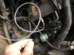
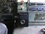
well I scooped out the guts of my dead ECU, carefull not to damage the cannon plug. Then I installed a 0-100PSI Automotive oil pressure gauge in the face, and 3 momentary pushbuttons on the top. I removed the passenger kickplate and unmounted the PCU so I could remove the bottom cover. This allowed me to get a wrench on and remove the pressure transducer. I capped it and re-attached it to the harness and zip-tied it to the harness in case I ever want to go back to an automated system. I installed the hose adapter compression fitting from the oil pressure gauge into the pressure port(it is 1/8” NPT) and re-installed the bottom cover and PCU. Using a fiberglass fish-tape, I fished the 1/8” poly oil pressure line thru behind the heater to below the park brake housing. Carefully marking where the pressure gauge port is on the ECU, I drilled a 3/8” hole behind where the ECU mounts for the line to reach the port on the back of the gauge I placed in the ECU. Mind the air lines inside the park brake compartment, none were in the area I chose to place the gauge, and I had plenty of clearance, but be carefull as you dont want to damage any of those.
On the cannon plug in the ECU, 24V is applied on pin H. Pin R, B and C leave the ECU to the solenoids on the PCU. Pin R is the Control solenoid, Pin B is the Supply solenoid and pin C is the Deflate solenoid. I connected pin H to the input of the control pushbutton. The output of the control pushbutton goes to pin R and also feeds the input of the supply and deflate pushbuttons. The output of the supply and deflate pushbuttons go to pins B and C respectively. Thats it, I will eventually add the gauge light to the output of the control pushbutton, but have not done that yet.
In order to operate correctly the PCU needs two solenoids activated together. I believe this was done to prevent a single short circuit or stuck valve from overinflating the tires. The resulting explosion from an over-inflated 47” split rim would be nothing short of catostrophic. If you go the manual route, this is one of those details you do not get a second chance to get right, so pay attention to how you manually inflate tires. That is why I used momentary pushbuttons. This requires fingers on 2 buttons to operate, and you cannot just turn it on and forget it...
How it operates:
As I mentioned, it needs two solenoids. In testing I discovered the Control solenoid by itself will slowly apply pressure, the Quick Release valves will squeel/ partially open at some point and eventually close as the pressure builds and eventually you will be left with tire pressure on the gauge once the wheel valves open. This takes 30+ seconds. Releasing control vents the system and all the valves close. Supply by itself jumps to tire pressure then decreases to a point where the QR valves start to squeel and dump. Deflate by itself does absolutely nothing but click the solenoid. Since it requires control, I wired the power to the supply and deflate buttons from the control button.
To Check pressure, depress and hold Control and momentarilly press Supply to apply air to the system and open the wheel valves. When you release Supply the gauge will stabelize on the current tire pressure as soon as the tires equalize.
To Inflate, depress and hold control then check initial pressure as described above. To inflate again press and hold the supply button along with control to feed high pressure air. The gauge will jump up around 80 PSI then drop rapidly to read 5+ PSI higher than the tires while filling. You can recheck actual pressure at any time by releasing the Supply button only. And of course this goes a little faster with increased engine RPM. You can press the Supply button as needed to top off the tires to the desired pressure.
To Deflate, Press and hold Control and then Supply briefly to check initial pressure. Then while continuing to hold Control, press and hold Deflate. This will cause the gauge to drop from current tire pressure to around 6-8 PSI. This drop causes the QR valves to open fully and start venting tire pressure to the atmosphere(woosh sound, not a squeal). To check pressure, release Deflate and momentarilly press Supply to close the QR valves and display current tire pressure...
In the first pic, I am holding the now capped presure transducer and harness in my hand and the compression fitting is installed in the port where the transducer used to live.
The second pic is the modified ECU housing with gauge on the face and new top plate and 3 buttons installed


Last edited:


