Hello everyone,
I thought I’d share with everyone how I replaced the battery charging regulator on my MEP-002a for cheep. Long story short, the charging systems on these generator sets are permanent magnet alternators, which are the same as used on motorcycles and scooters, except for the 24V output.
The regulator does two functions – first it rectifies the raw AC coming from the stator coils into DC, then it shunts (or shorts) the stator coils together (or to ground) when the battery voltage gets above the desired setpoint. The reason for shunting is that these alternators have constant output due to the permanent magnets and it cannot be controlled by varying the magnetic field strength, as is done with a normal automotive alternator.
So, order yourself a 12V “5 wire scooter voltage regulator”. I got mine on ebay for $4.49 including shipping from China. I have no idea how they make them that cheap… Below is a link to the one that I bought.
link removed...
The 5 wire version has a separate wire for the voltage sensing circuit so that it can be hooked to a keyed switch and not constantly draw a few milliamps and drain the battery over time. This is the black wire on the regulator. The pink and yellow wires are the two wires coming in from the stator coil (raw AC). The red wire is the DC output wire, which goes through the 15 amp fuse for the charging system. The green wire is a ground wire and is tied to the chassis of the generator. I got the wiring info for this regulator from here --> http://mastercircuits.blogspot.com/2012/07/full-wave-regulator-schematic.html The author does a dissection of the 5 wire regulator. If you follow the link and check the part number for the rectifier bridge that he shows in the pics, you will note that it is a 25 amp, 400V device. The SCR’s in the circuit that short the windings have to be similar in amperage and voltage, so the voltage and current of our generator charging system shouldn’t be an issue (max output is 15 amps).
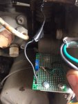
To make a 12v scooter regulator work on our 24v system, you need a voltage divider circuit. This is simply two resistors wired end to end (in series), with 24v battery power at one end of the resistor string and ground at the other end. I used a 0~1000 ohm potentiometer (variable resistor) connected to a fixed 850 ohm resistor. You hook the black wire of the regulator up to the middle point in between the two resistors. I used ½ watt components in my setup, as this is what I had laying around. I calculated the power dissipated by both resistors as 0.488 watts, so ½ watt should be OK. Nothing got warm when I tested it…
The potentiometer allows you to fine tune your final output voltage. I have mine set to 27.6 volts because I use AGM batteries. If you use standard flooded batteries, adjust yours to 28.8V with the engine running and the batteries fully charged.
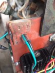
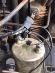
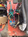
I mounted the scooter regulator in the same location as the original voltage regulator, as there is good airflow and the terminal strip is there to hook everything up. The scooter regulator is about half the size as the original regulator. I ran the black wire to the other side of the plate and mounted my voltage divider circuit outside of the doghouse so that I can adjust it. I took keyed power from the shutoff solenoid at the injector pump. While I was at it, I installed a snubber diode across the terminals of the shutoff solenoid. This gets rid of the inductive voltage spike that you get when you disconnect power to a solenoid coil, so the electronics should live a happier life.
I tested everything out yesterday and it seems to do fine. I monitored battery voltage as the genny ran for about an hour, and the charging system charged up after using power for startup (battery dropped to 22-23V and leveled out to setpoint, 27.6V. Before I replaced the regulator, the battery voltage was up to ~31V as the regulator wasn’t working.
Hope this helps some other folks out.
Kevin
Last edited by a moderator:


