dependable
Well-known member
- 1,720
- 188
- 63
- Location
- Tisbury, Massachusetts
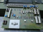
I decided to get an 002 out of storage and run, since it has been a while. This is a low hour unit(89) that has been stored in shipping container so no weather or rodents. Cleaned up fuel system, checked IP plunger etc. Hooked up good batteries, primer and heater work, but would not crank.
I went though steps and tested S1 switch per TM, and continuities on start circuit tested good.
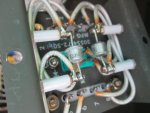
Also tested continuity to ground on K-3 ground circuit. And tested and found there is no voltage to positive K-3 circuit (actuating terminal) when in crank position.
If I jump solenoid w screwdriver it cranks over, when I jump K-3 stater relay it cranks over, and it will start and run fine if I holding start switch over to actuate fuel solenoid.
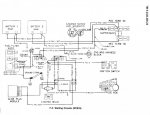
I have spent some time re familiarizing w TMs and looking at wire diagram, but may be missing something, since I tested S1 and there is also no reason for it to go bad stored dry & safe.
Are there any circuits or switches between S1 and K3 that I am missing?
I did check starter lockout switch and it looks fine, points clean & closed. Also tried bypassing it, just in case.
I went though steps and tested S1 switch per TM, and continuities on start circuit tested good.
Also tested continuity to ground on K-3 ground circuit. And tested and found there is no voltage to positive K-3 circuit (actuating terminal) when in crank position.
If I jump solenoid w screwdriver it cranks over, when I jump K-3 stater relay it cranks over, and it will start and run fine if I holding start switch over to actuate fuel solenoid.
I have spent some time re familiarizing w TMs and looking at wire diagram, but may be missing something, since I tested S1 and there is also no reason for it to go bad stored dry & safe.
Are there any circuits or switches between S1 and K3 that I am missing?
I did check starter lockout switch and it looks fine, points clean & closed. Also tried bypassing it, just in case.
Last edited:


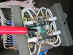
 Now thank goodness the mystery has been solved.