bmchauvette
New member
- 9
- 7
- 3
- Location
- Easley sc
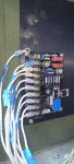
MEP. 003A.VR. Pinout. my generator was putting ouT power until one day it just stopped for no apparent reason
I believe my helper installed the Avr board Incorrectly. So I must do a pin out to trace the wires. I don't think the schematic is correct. I am working off the schematic in TM. 5-6115-585. Dash 34. Change #5. Terminals one, two, and three are jumped together. 8&9 are also jumped, but I don't have any Jumpers on my board also My board is fully populated (no unused terminals). However, terminal 6&7 Is not used on the schematic.
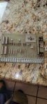
I am going to use a tone tracer To check out the installation. Any pointers? I noticed that three of the six rotating diodes are reverse-biased (Noted on the schematic). Can I read the printing on the old diodes to tell which ones are reversed? Or how can I tell which ones are reversed bias? Do the diodes need to be disconnected to test? Is it safe to assume diodes of a higher voltage and current rating are OK to use?
I believe my helper installed the Avr board Incorrectly. So I must do a pin out to trace the wires. I don't think the schematic is correct. I am working off the schematic in TM. 5-6115-585. Dash 34. Change #5. Terminals one, two, and three are jumped together. 8&9 are also jumped, but I don't have any Jumpers on my board also My board is fully populated (no unused terminals). However, terminal 6&7 Is not used on the schematic.
I am going to use a tone tracer To check out the installation. Any pointers? I noticed that three of the six rotating diodes are reverse-biased (Noted on the schematic). Can I read the printing on the old diodes to tell which ones are reversed? Or how can I tell which ones are reversed bias? Do the diodes need to be disconnected to test? Is it safe to assume diodes of a higher voltage and current rating are OK to use?