• Steel Soldiers now has a few new forums, read more about it at: New Munitions Forums!

  • Microsoft MSN, Live, Hotmail, Outlook email users may not be receiving emails. We are working to resolve this issue. Please add support@steelsoldiers.com to your trusted contacts.


MEP 003A Frequency Transducer

dangier

Member
341
7
18
Location
Page County, VA
Might be a dumb question, but has anyone been successful in adjusting the zero and span on the 002 or 003 frequency transducer? I have one that reads high and I would like to try recalibration. TM's are no help that I could find (both 002 and 003 manuals).
David
 

Keith_J

Well-known member
3,657
1,314
113
Location
Schertz TX
The transducer converts frequency into current, 60 Hz should be 100 microamperes. Of course you have to check both transducer and meter. But in reality, all you need to have is the meter reading 60 Hz. What I do is pull both, then rig up a test using utility power on the input to the transducer and hook the meter up as if it were installed in the generator.

Be careful, do NOT short the transducer output and remember, you have 120 volts on the input to the transducer. The meter is VERY delicate, electrically speaking. Do NOT connect ANY current source to it, even a multimeter set to measure resistance can be too much current.
 

PeterD

New member
622
6
0
Location
Jaffrey, NH
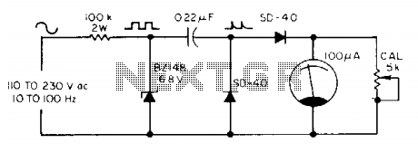
The transducer converts frequency into current, 60 Hz should be 100 microamperes...
Great comment, Keith. Let me add:

First there are several versions of the meter/transducer pairs. Not all are 60 Hz to 100 µA, some are different. :-? So don't go mixing meters and transducers--they are a matched pair.

Second the actual meter adjusting screw is for zero set only, and should not normally be used to get a given or specified reading. If the meter is zero'ed with no current, and doesn't read the specified value with the rated current, the meter is defective.

Third, some of the transducers are adjustable. Some (early ones, typically are not.) The adjustable ones can be 're-calibrated' if their accuracy is questionable. Personally I recalibrate to 60 Hz and don't bother even checking the 50 Hz specification since no one here in the US needs a 50 Hz generator set! Keith's using of line voltage to calibrate is what I do as well--it works quite nicely. I also have used, but don't recommend, an audio signal generator, feeding an amplifier to check various frequencies, but I did that just to see how things worked!

Also, just for the record: that frequency meter is nothing more than a standard electronic tachometer. The transducer is a simple chip (today) and could be easily be replicated if one wanted.
 

Ray70

Well-known member
2,379
5,100
113
Location
West greenwich/RI
Here is a similar thread from a couple weeks ago talking about the transducers and meters.
I know next to nothing about electronics, but, just like it was mentioned in this other thread, it would be fantastic if one of the electronics guru's on this site could come up with a simple, innexpensive board or component that could replace the faulty frequency transducer and allow us purists to continue to use our outdated analog HZ meters.
Possibly Peter's electronic tachometer chip would be a possibility?? Anyone feel up to the task?
http://www.steelsoldiers.com/showthread.php?122458-mep-006a-hertz-problem
 

cuad4u

Active member
268
88
28
Location
St Matthews, SC
I had a similar problem with one of my 002A's and I "fixed" it with a 5 cent resistor. The built in Hz meter read 65Hz when the Fluke 87 VOM indicated 60Hz. Since I (like most everybody else) am only interested in getting an accurate Hz reading at or very near 60Hz, I added a resistor in series with the built in Hz meter until it read 60Hz when the Fluke read 60Hz. I found the right resistor value by trial and error. Another way is to put a pot (potentiometer) in series with the built in Hz meter and adjust the pot until the built in Hz meter agrees with the Fluke 87. Measure the resistance of the pot and substitute a fixed value resistor.

After I installed the resistor the built in Hz meter tracked perfectly with the Fluke 87 meter from 58-62Hz. It varied a little bit over and under these values. But then I am only interested in good accuracy around 60Hz +/- 2Hz.
 

Ray70

Well-known member
2,379
5,100
113
Location
West greenwich/RI
A quick Google search turned up this circuit design for a frequency meter. Being that the MEP's use 200uA gauges, could this circuit be modified ( possibly by changing the resistor value ) to work correctly with the OEM gauge?
 

dangier

Member
341
7
18
Location
Page County, VA
Update-set up transducer and freq meter on bench using household power and just a little tweak brought the meter at 60 hz.
siliconed over the adjustment screw, reinstalled everything and started unit up. Adjusted to 60 hz and the hz output agrees with my handheld meter. Right on!
David
 

PeterD

New member
622
6
0
Location
Jaffrey, NH
A quick Google search turned up this circuit design for a frequency meter. Being that the MEP's use 200uA gauges, could this circuit be modified ( possibly by changing the resistor value ) to work correctly with the OEM gauge?
Bottom line, this is a simple circuit and would not be ideal. There is a tachometer IC (if I remember I'll look it up) that would do much better. But the answer to your question would be yes, you could tweak it to work.
 

GREENMV

New member
Steel Soldiers Supporter
325
5
0
Location
Linden, TN
@dangier, I tried that once and it didn't last long for me. the fine screw adjustments seem to lose contact from the vibration. The transducer is a piece of junk "Deep Six" If someone could make a replacement I sure would buy some. :popcorn:
 

GREENMV

New member
Steel Soldiers Supporter
325
5
0
Location
Linden, TN
I have made a digital V/Hz meter that I to use for setting Generators and I use it also inside the house. I plug it into an outlet to keep an eye on volts and Hz when running.photo 2 (2).jpgphoto 1.jpgphoto 2.jpgphoto 3.jpg
 

Ray70

Well-known member
2,379
5,100
113
Location
West greenwich/RI
Looks very familiar.... I have the same gage on one of my units too. I had cut out an adapter plate and mounted it in place of the analog gage.
I recently lost yet another transducer on my other machine and was interested in a way to drive the original gage,( just for authenticity) and have a plug in gage for better accuracy.
 

Ray70

Well-known member
2,379
5,100
113
Location
West greenwich/RI
This morning I threw together a test board using the schematic I posted Friday and it worked... sort of....
The 5K potentiometer is way too big and sensitive. I ended up needing about 30 ohms at 60hz so I replaced it with a 200 ohm pot that I found and it works great so far, just sitting on a bench. But, like PeterD said, there is apparently a better, more reliable chip that will do the same thing.

Peter, if you have time to look into it at all, please post anything you can find about the tachometer chip and associated circuitry.
 

Ray70

Well-known member
2,379
5,100
113
Location
West greenwich/RI
So, the other day I hollowed out one of my dead transducer bodies ( found a bunch of stuff buried inside the potting material ) looks like it had not only a circuit board, but also a transformer or coil and a pair of caps about the diameter of a AA battery down the bottom.
I made another board that will fit snugly in the empty can, diagonally from corner to corner and will wire it to the existing screw terminals on the can, just waiting for a delivery (hopefully today ) of the correct 100K 2W resistors, my sample board was made with four 1/2W resistors in parallel. Once its put together I'll attach a cord to it and plug it into one of my 002A's and see if the readings it gives at frequencies above and below 60hz are at all close to what the digital meter says. If its reasonable close I'll probably install everything back into the generator and leave the analog gage in the machine and put the digital gage on a cord so it can be used both on the generator and in the house like GreenMV did. Would be nice to watch the power from in the house, incase something goes wrong. I'd like to use the tachometer circuit that PeterD mentioned instead, but so far have not been able to find any info on it.
 

dangier

Member
341
7
18
Location
Page County, VA
Ray-Fascinating information. Waiting to see how you come out. I use a Blue Sea System multimeter to monitor in the house voltage and frequency (part of the better half's training to run the emergency genny in case I am not around).
David
 

cuad4u

Active member
268
88
28
Location
St Matthews, SC
I have a couple of MEP gens with bad transducers. I have tried several different alternatives without much success. While cruising ebay I noticed some NOS vibrating reed type Hz meters for sale. They are the sealed type meters that should survive in the MEP. I think there still may be some listed. Some registered from 55-65 and some registered from 58-62. They all had the same 3 screw mounting pattern as the original MEP meters. I bought a couple for $12 each and installed them. They work perfectly. Just another way to do it.
 
Top
AdBlock Detected

We get it, advertisements are annoying!

Sure, ad-blocking software does a great job at blocking ads, but it also blocks useful features of our website like our supporting vendors. Their ads help keep Steel Soldiers going. Please consider disabling your ad blockers for the site. Thanks!

I've Disabled AdBlock
No Thanks