• Steel Soldiers now has a few new forums, read more about it at: New Munitions Forums!

  • Microsoft MSN, Live, Hotmail, Outlook email users may not be receiving emails. We are working to resolve this issue. Please add support@steelsoldiers.com to your trusted contacts.

MEP-003a losing power

crawdadjr

New member
10
0
0
Location
Jacksonville, Fl
I have a MEP-003a that stopped making power last week. Following the Tech manual and help from Triple Jim determined I had a faulty voltage regulator. Bench troubleshooting revealed faulty Q3, Q1 and Q2 had different signatures using a Huntron tracker, so replaced all three transistors. Re-installed the VR and had good voltage and worked with no issues for approx 2 hours. Lost power and troubleshooting revealed the VR again. Using a huntron again revealed Q3 faulty again. Re-installed the VR this afternoon and fired up the generator had 60hz 115v on the gauges for about 6-8 min then lost it. Shut it down for a few minutes and re-started it, gauges read good freq and voltage for approx 2 min then went back to zero. I hate intermittent issues!
Has anybody else seen a genset do this? What can cause Q3 to bad like that? Possibly something else on the VR?
Thanks in advance.
 

Farmitall

Well-known member
Steel Soldiers Supporter
544
276
63
Location
Eubank, KY
I'd be checking for cold solder joints on everything on the board and reflow anything even remotely suspect, particularly anything in the path of Q3. If the VR board has a terminal strip check those connections first.
 

Kenny0

Active member
121
30
28
Location
Leland, Iowa
Also check the volt adjustment knob. With engine off, turn knob back and forth with electronic cleaner to clean up contact inside.
 

crawdadjr

New member
10
0
0
Location
Jacksonville, Fl
Thanks for the info, I looked at the volt adj resistor it is a sealed unit but I verified operation with a multimeter and it doesn't have any dead spots on it. Resistance varies from all the way from one end to the other. I also verified CT1 and CVT1 resistance checks per TM -34. I think I have blown Q3 on the VR again because now I have zero voltage with the genset normalled up. I lifted pin 17 from the VR (removing it from the system) and have good voltage 150v and good freq. Still points back to the VR, I going to follow farmitall recommendation and pull the VR, replace Q3 again and re-flow ALL solder joints.
 

Guyfang

Moderator
Staff member
Moderator
16,923
24,544
113
Location
Burgkunstadt, Germany
Have you talked to Triple Jim? I just mailed someone I know who might be able to help, but those Gub-mint boys go home early.
 

crawdadjr

New member
10
0
0
Location
Jacksonville, Fl
I have been talking with Triple Jim, I PMd him after reading another thread because I didn't want to hijack the thread. I am going to pull the VR tomorrow but it will be next week before I get it looked at. I can use all the help I can get.
Thanks
 

Dieselmeister

Well-known member
Steel Soldiers Supporter
198
276
63
Location
Flagstaff, Az
I am relatively new to the MEP-802, but here are some thoughts.
When you are cranking (with the field flash relay energized) are you getting any voltage on the QUAD windings?
Any chance you have a shorted diode on the VR, and are getting AC voltage into the semiconductors?
Any chance you have a intermittent short in the Field wiring? If the wires going to the field short out, your output voltage drops, and the VR will send more current trying to get the voltage back up. This could overload the VR, and fry the components if the short is bad enough. You could add a temporary fuse to the field wires to troubleshoot that theory, after you rebuild the VR.
One of these days, I will pull my VR, and reverse engineer it to make a schematic. That would make troubleshooting much easier. Looking at the VR pictures on the Forum, it looks like a pretty simple circuit.
 

crawdadjr

New member
10
0
0
Location
Jacksonville, Fl
When you say field wiring are you talking about the exciter field? I pulled J12 connector and checked a couple of days ago and had 35ohms. I plan on having the whole VR gone thru next week, I may end up getting one from Triple Jim anyways! I keep everyone updated once I get the VR back.
 

Dieselmeister

Well-known member
Steel Soldiers Supporter
198
276
63
Location
Flagstaff, Az
Yes, I was referring to the exciter field wires that go from the A1 VR terminals 5&6 down to the exciter stator. 35 ohms seems high. The TM shows 10.54 to 14.26 ohms for the stator leads in table 4.1.
 

Guyfang

Moderator
Staff member
Moderator
16,923
24,544
113
Location
Burgkunstadt, Germany
I am relatively new to the MEP-802, but here are some thoughts.
When you are cranking (with the field flash relay energized) are you getting any voltage on the QUAD windings?
Any chance you have a shorted diode on the VR, and are getting AC voltage into the semiconductors?
Any chance you have a intermittent short in the Field wiring? If the wires going to the field short out, your output voltage drops, and the VR will send more current trying to get the voltage back up. This could overload the VR, and fry the components if the short is bad enough. You could add a temporary fuse to the field wires to troubleshoot that theory, after you rebuild the VR.
One of these days, I will pull my VR, and reverse engineer it to make a schematic. That would make troubleshooting much easier. Looking at the VR pictures on the Forum, it looks like a pretty simple circuit.

wrong gen set. He has a MEP-003A. But good answer for the TQG. Someone should reverse engineer the VR.
 

Guyfang

Moderator
Staff member
Moderator
16,923
24,544
113
Location
Burgkunstadt, Germany
Yes, I was referring to the exciter field wires that go from the A1 VR terminals 5&6 down to the exciter stator. 35 ohms seems high. The TM shows 10.54 to 14.26 ohms for the stator leads in table 4.1.
And what does the TM say you should do if the Excitor field wires ohm out not IOW the TM?
 

crawdadjr

New member
10
0
0
Location
Jacksonville, Fl
I went back and re-verified my exciter field wiring resistance and if I am reading it correct, TM-34 Chap 8 pg 4 para f, says the resistance should be 36 ohms, I am reading 35ohms. I have not checked it to ground so I will try that this afternoon. Everything is leading me to the VR but I am just trying to rule everything else out. while I am waiting on the VR.
Thanks for the responses.
 

justacitizen

Active member
408
40
28
Location
oklahoma
just a shameless plugg. but tripplejim makes a bulletproof replacement VR for this generator. he also makes an excellent DC VR same same
 

Guyfang

Moderator
Staff member
Moderator
16,923
24,544
113
Location
Burgkunstadt, Germany
Have you talked to Triple Jim? I just mailed someone I know who might be able to help, but those Gub-mint boys go home early.

This is the answer I got back from someone who is the BOSS at these sets.


Guy:

Yes. Several times and this is a hard one to actually find unless you play parts changer. The Q3 is in saturation. It overheats and the inside crystal structure breakdown. Reason for saturation is usually trying to maintain a field voltage to maintain 120VAC. I never trusted the eyeball trick. Did the easy stuff first as it takes no time and it goes fast. R1 field windings and such. Once I cancelled out the main gen then comes all the junk in the box. I would actually test the components on the regulator. One I had I found a solder trace bad causing the issue. Then the diode and resister board where the resistor usually changes values and pops a diode. Then transformers especially swollen ones and finally the wiring. Had bad components in each of those at one time or another usually because of vibration and insulation wear thru or corrosion. That one is a pain.


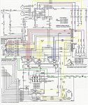
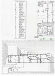
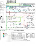
He also sent a few other things you might find interesting. The last one is a file with all the three previous one in it. If you pay close attention, you will find many notes written on these sheets, that ARE NOT in the TM's.


10KW MilStd AC1.jpg

10KW MilStd AC2.jpg

10KW MilStd DC.jpg

View attachment 10KW Mil Std Schematics.pdf
 
Last edited:

Chainbreaker

Well-known member
1,802
2,010
113
Location
Oregon
Thanks guy! I really like those color coded circuits! I downloaded and installed on my tablet for future genset trouble shooting usage. I also have the big "D" size printed schematic but no color coding unfortunately.
 

Triple Jim

Well-known member
1,376
293
83
Location
North Carolina
This is the answer I got back from someone who is the BOSS at these sets.

It overheats and the inside crystal structure breakdown. Reason for saturation is usually trying to maintain a field voltage to maintain 120VAC.
Q3 doesn't have much heat sinking on the board, so I don't doubt that it could overheat if it were asked to supply a lot of current, but:

The regulator does not supply current to the exciter field, it only sends a small current, less than 400 milliamps, though the control winding of CVT1. When the regulator senses a need to increase field current, it reduces its output to CVT1's control winding.

This is proven by disconnecting the regulator completely, and observing that the output voltage goes considerably above normal. That happens because CVT1 then supplies full output current to diode board A4, which in turn sends the DC out to the exciter field.

If for example CVT1 has a problem with its control winding, like it's shorted and not working as designed, the regulator would try like heck to reduce generator output by increasing its output current to the point of overheating Q3.
 
Top
AdBlock Detected

We get it, advertisements are annoying!

Sure, ad-blocking software does a great job at blocking ads, but it also blocks useful features of our website like our supporting vendors. Their ads help keep Steel Soldiers going. Please consider disabling your ad blockers for the site. Thanks!

I've Disabled AdBlock
No Thanks