• Steel Soldiers now has a few new forums, read more about it at: New Munitions Forums!

  • Microsoft MSN, Live, Hotmail, Outlook email users may not be receiving emails. We are working to resolve this issue. Please add support@steelsoldiers.com to your trusted contacts.

Mep-004 making no electric

Knjs

New member
22
14
3
Location
New Jersey
when you start the set hold the switch to start for several seconds and see if that gives you any power (these have an electric flash circuit and is a common mistake when starting) also make sure you have some throttle, DO NOT idle these sets.

Further troubleshooting to follow once you try this
Yes, with each start I hold in the start position till a few seconds after oil pressure builds. I have had several mep-005s so I am slightly familiar with there operation. On my 5's the voltage gauge will read even if the switches are in the wrong position and it has no output but this one reads nothing.
 

Knjs

New member
22
14
3
Location
New Jersey
when you start the set hold the switch to start for several seconds and see if that gives you any power (these have an electric flash circuit and is a common mistake when starting) also make sure you have some throttle, DO NOT idle these sets.

Further troubleshooting to follow once you try this
Out of curiosity what is the reason to not let these units idle ? Even if there is nothing drawing on it?
 

Scoobyshep

Well-known member
1,192
1,663
113
Location
Florida
Out of curiosity what is the reason to not let these units idle ? Even if there is nothing drawing on it?
Bad practice. When they are producing power and the engine is at idle it puts alot of undue strain on the voltage regulator. This will eventually damage it. Its always best to avoid idling
 

Knjs

New member
22
14
3
Location
New Jersey
Bad practice. When they are producing power and the engine is at idle it puts alot of undue strain on the voltage regulator. This will eventually damage it. Its always best to avoid idling
Ok. That makes sense. Is there one regulator for each of the 3 legs or all 3 legs go threw one regulator?
 

Scoobyshep

Well-known member
1,192
1,663
113
Location
Florida
Yes, with each start I hold in the start position till a few seconds after oil pressure builds. I have had several mep-005s so I am slightly familiar with there operation. On my 5's the voltage gauge will read even if the switches are in the wrong position and it has no output but this one reads nothing.
On the right side of the set, int the front compartment there is a terminal board, (only 2pairs) this is the connection for the field windings. check voltage here while you have a helper hold the switch to start.
 

jamawieb

Well-known member
1,436
557
113
Location
Ripley/TN
More than likely the exciter box or some call it the VR box. Its located on the starter side above the generator head. Its the box that has louvers. 99% of the time the T2 transformer fails and destroys itself. Usually you can look through the louvers to see if it looks burned inside. You can take the box off a 005 and switch them to try out my theory. Then you can work from there. If it is the VR box, I did a write up on converting a 005a to a modern VR which eliminates alot of failure points.
 

Guyfang

Moderator
Staff member
Moderator
17,052
24,950
113
Location
Burgkunstadt, Germany
The glass fuse has nothing to do with nothing. Its for the fault indicator. All electrical parts are the same between the 005 and 004. The Terminal strip Scobby was talking about is TB16. It only has 2 terminals. The wires are F1 and F2. Measure between them while someone else starts the set and hold the S2, (Start Switch) in the up position. You should get 24 VDC.

Next, you can, if you want, take the A11, (static exciter box) mentioned by Jamawieb out and look at the Volt regulator card, and the Transformers, to see if they are burnt. But sometimes there is no "burnt" items. They are just bad.

I would first take out the A27, (Special Relay box) out and look at the A5, (DC Relay assy) Card. See if it has burn marks on the card. The K5, (Field Flash Relay) is mounted there. If it gets no signal from the S9-1, pin C, (Speed Switch) Then the A11 will not work.

To test the S9-1 circuit, I would use a MM, (multi meter).
1.Get a Alligator clip attachment for one lead on the meter.
2. Take the bottom off the A27. Hook the clip to A5-13.
3. Hook all the C-Plugs back up to the A27.
4. Have someone start the gen set, and hold S2 in the up position for at least 15-20 seconds, while you hold the other lead to the MM on ground. You should get 24 VDC

Also, all the gen set TM's are here in the TM forum. If you need help finding them, say something.
 

Knjs

New member
22
14
3
Location
New Jersey
More than likely the exciter box or some call it the VR box. Its located on the starter side above the generator head. Its the box that has louvers. 99% of the time the T2 transformer fails and destroys itself. Usually you can look through the louvers to see if it looks burned inside. You can take the box off a 005 and switch them to try out my theory. Then you can work from there. If it is the VR box, I did a write up on converting a 005a to a modern VR which eliminates alot of failure points.
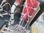
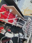
I know it's been awhile but I finally got into the excitation box and found 2 broken wires, cr1 and cracked just to the right of the plugs. Cr1 looks like it grounded itself out after it broke. Do you think it burnt something else out or it I soldered them back should they be ok?
 

Attachments

Knjs

New member
22
14
3
Location
New Jersey
More than likely the exciter box or some call it the VR box. Its located on the starter side above the generator head. Its the box that has louvers. 99% of the time the T2 transformer fails and destroys itself. Usually you can look through the louvers to see if it looks burned inside. You can take the box off a 005 and switch them to try out my theory. Then you can work from there. If it is the VR box, I did a write up on converting a 005a to a modern VR which eliminates alot of failure points.
Well soldering the wires back on did not fix it. I guess next time I get a chance I'll grab the exciter box out of my other unit (005) at my parents and try that.
 

Knjs

New member
22
14
3
Location
New Jersey
Thats the Beauty of the 004 and 005! Now, take a look at the card mounted there. See any hot spots? See any damage?
I didn't notice any. Besides where the top wire grounded its self to the mounting bolt. That's why I was asking if it could've burnt something else out. Is there any chance of burning out my other exciting box? My only real fear of swapping for known good parts.
 

Attachments

Top
AdBlock Detected

We get it, advertisements are annoying!

Sure, ad-blocking software does a great job at blocking ads, but it also blocks useful features of our website like our supporting vendors. Their ads help keep Steel Soldiers going. Please consider disabling your ad blockers for the site. Thanks!

I've Disabled AdBlock
No Thanks