• Steel Soldiers now has a few new forums, read more about it at: New Munitions Forums!

  • Microsoft MSN, Live, Hotmail, Outlook email users may not be receiving emails. We are working to resolve this issue. Please add support@steelsoldiers.com to your trusted contacts.

MEP-004A, No output

peapvp

Well-known member
Steel Soldiers Supporter
1,139
1,294
113
Location
Basehor, KS
I was not able to post a direct link to the parts for whatever reason, but here are the Part Numbers for A5 R3:

Inductive Version:
Mfr. #: RS0101K500FB12 Mfr.: Vishay / Dale

Non Inductive Version:
Mfr. #: NS0101K500FB12 Mfr.: Vishay / Dale

I am going to attache the Datasheets here to this post below

Now the original Resistors on A5 where of two types:

R3, R7, R8 = UT (smaller 10W)

and

R6 and R9 = IRC SX (IRC RW Type 14W)


View attachment UT.pdfView attachment rsns-226497.pdfView attachment IRCID00004-151.pdf


peapvp

Well-known member
Steel Soldiers Supporter
1,139
1,294
113
Location
Basehor, KS
Guy you may have to jump in here. I know that new MIL-STD Conformal Coating we use now is not compatible with the old one. I have not been able to find any info on the coating they used in the 60's and 70's.

On some of those old coatings isopropyl alcohol works as stripper, the plastic parts are resistant to that.
Any silicone based conformal coating will work to re-coat the board once it has been stripped.

The stuff I use is the current Coating the Military requires and is silicone based, uv resistant, anti fungal and works from -55C to +125C and costs $135.00 / quart (1 L) which is the smallest unit available (besides 1 Gal and 5 Gal)

Guyfang,

Once I replace R3 and R8 A5 resistors what would you coat the solder with?
Kris
 

peapvp

Well-known member
Steel Soldiers Supporter
1,139
1,294
113
Location
Basehor, KS
This brings me to another part on A5 - the relays (before anyone asks):

Those are Mil-Std relays - they are made by TE-Connectivity

5945-00-435-1833

Mfr. #: B07D634BC2-0051 Mfr.: TE Connectivity

Mouser has them listed with a 5 day lead time for US$ 223.72/ea

current US Stock 5pcs at TE-Connectivity ( who bought Tyco / Amp )

Those Relay's are very difficult to cross reference because of the socket connection

Here are the specs:


TE Connectivity


Product Category:
General Purpose Relays


RoHS:


Product:
Power Relays


Type:
Non-Polarized


Coil Voltage:
26.5 VDC


Relay Contact Form:
2 Form C (DPDT-NO, NC)


Contact Current Rating:
10 A
(Original Rating 1974: 5.0 amperes ac resistive load and 6.0 amperes dc resistive load)


Contact Termination:
Plug Pin


Mounting Style:
Through Hole


Coil Termination:
Solder Lug


Coil Type:
Non-Latching


Coil Resistance:
300 Ohms


Contact Material:
Silver Cadmium Oxide (AgCdO)


Series:
07


Length:
27.3 mm


Width:
15.9 mm


Height:
25.7 mm


Contact Form:
DPDT (2 Form C)


Power Consumption:
2.341 W


Brand:
TE Connectivity


Product Type:
General Purpose Relays


Factory Pack Quantity:
1


Subcategory:
Relays


Part # Aliases:
2-1617004-8


Unit Weight:
1.128767 oz


Last edited:

Guyfang

Moderator
Staff member
Moderator
17,032
24,899
113
Location
Burgkunstadt, Germany
In some instances only one set of contacts are used. So you can turn them 180 degrees, plug them in and they work. Any older gen set that has been raped for parts, is a good source for them. In a pinch, for the Mep-004 up to the MEP-007, you can open up the fault indicator and use the one in there. The relays are fairly robust. But every now and then they fail.
 

KLChurch

New member
475
2
0
Location
Montgomery/TX
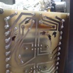
Just uninstalled R3 and R8 from the A5 board. They were not easy to take off. Seems the installer bent the wires after poking them through the holes. So I had to grind the solder off and grind the bent portion of the wire. Then they came right off. So this maybe a heads up if anyone wants to replace toasted resistors.

I tested the relays before and they were OK
Kris
 

KLChurch

New member
475
2
0
Location
Montgomery/TX
Also when I was flipping the start switch, I had to flip it a lot more now before the starter engaged. Could this be the switch possibly going bad?
Kris
 

peapvp

Well-known member
Steel Soldiers Supporter
1,139
1,294
113
Location
Basehor, KS
Interesting concept. Would be also very interesting to see a picture off solder removal with a grinder. How did the Circuit Board track fair in this?
Peter


Just uninstalled R3 and R8 from the A5 board. They were not easy to take off. Seems the installer bent the wires after poking them through the holes. So I had to grind the solder off and grind the bent portion of the wire. Then they came right off. So this maybe a heads up if anyone wants to replace toasted resistors.

I tested the relays before and they were OK
Kris
 

KLChurch

New member
475
2
0
Location
Montgomery/TX
a5 back desolder.jpga5 r3.jpg
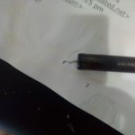
The second pic is R3. As you can see the end of the wire is bent.
This is the one I discovered the wires where bent. It took a **** of a lot of force to pull it out.
So it took a couple beers to think how I'm going to remove them without destroying other parts.

In pic two if you look close where R8 was removed you can see my grind marks using a dremel with the smallest cutoff grinding wheel I had.
I had to be very carful not to let it skip across the board so I just barely ground maybe .005 inch per stroke until I could see the board hole with the wire in it.
After that just pull the resister out.
The ink marks were to remind me where to locate the suckers.
The solder was about .0625 tall so you have to be very focused and patient.
Kris
Kris
 

peapvp

Well-known member
Steel Soldiers Supporter
1,139
1,294
113
Location
Basehor, KS
Kris,

Usually the best way to get those parts out is by cutting the leads on the component side, then using a solder iron heating up the solder pad and when the solder is hot and flowing, pushing the lead out from the top / component side with a pair of tweezers or needle nose pliers. It usually just falls out by itself this way -


The second pic is R3. As you can see the end of the wire is bent.
This is the one I discovered the wires where bent. It took a **** of a lot of force to pull it out.
So it took a couple beers to think how I'm going to remove them without destroying other parts.

In pic two if you look close where R8 was removed you can see my grind marks using a dremel with the smallest cutoff grinding wheel I had.
I had to be very carful not to let it skip across the board so I just barely ground maybe .005 inch per stroke until I could see the board hole with the wire in it.
After that just pull the resister out.
The ink marks were to remind me where to locate the suckers.
The solder was about .0625 tall so you have to be very focused and patient.
Kris
Kris
 

peapvp

Well-known member
Steel Soldiers Supporter
1,139
1,294
113
Location
Basehor, KS
Btw. Kris, do you have the right solder to put the new resistors on the board?

the best and most suitable solder is SNPB 63/37 with rosin core flux
 

KLChurch

New member
475
2
0
Location
Montgomery/TX
solder.jpg

This is the solder I used on the yellow wires. Home Depot

The wires are still connected to A5.
So it would be best to disconnect all the wires and de-solder your way.
I agree but I did not do it that way. Your way is better.
Kris
 

peapvp

Well-known member
Steel Soldiers Supporter
1,139
1,294
113
Location
Basehor, KS
This solder is Ok as it has a rosin core (flux) - however, Military and Industrial components have leads/pins which contain lead. Besides, SNPB (Lead based solder) flows better and creates a better, more durable connection.
Only consumer grade parts are lead free today - mostly because of California Proposition 65....
but it doesn't solder as well....
 

KLChurch

New member
475
2
0
Location
Montgomery/TX
Good you relieved my mind. I was wondering if it was good enough. But also I used an external flux to make sure it spread where I needed it to. That is sold at the same place and used to solder copper pipes together.
The solder I used has flux in the core.
Kris
 

Guyfang

Moderator
Staff member
Moderator
17,032
24,899
113
Location
Burgkunstadt, Germany
View attachment 774794

This is the solder I used on the yellow wires. Home Depot

The wires are still connected to A5.
So it would be best to disconnect all the wires and de-solder your way.
I agree but I did not do it that way. Your way is better.
Kris
Kris,

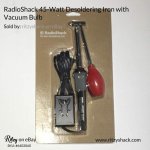
There is also a tool called a solder remover. It is an attachment that goes on, or replaces your soldering iron tip. What it does is heat up the solder, (just like your normal soldering iron) and when the solder flows, you press a big rubber bulb, (Kinda like a kids toy tricycle horn) and blow away solder. Or, you press the bulb slowly, and when the solder flows, let the bulb go, and the vacuum sucks off the solder from your solder point. If It wasn't 23:24 I would go out to the garage and get one to show you a picture. Takes a little practice too use, but once you master it, its pretty darned handy.
 

KLChurch

New member
475
2
0
Location
Montgomery/TX
Guy,
You are very correct. I saw them on Amazon and thought I should buy one a couple years ago when I was creating my drones. But I didn't buy one.
Kris
 

KLChurch

New member
475
2
0
Location
Montgomery/TX
If I had a wish list the first thing I would buy is a super heavy duty third hand. Everything on Amazon so far I have seen is trash and will tip over with one ounce of force. This would make de soldering and soldering a lot more easier. It needs to be able to hold a board in place rigidly. Maybe I'm looking in the wrong place in Amazon.
Kris
 

peapvp

Well-known member
Steel Soldiers Supporter
1,139
1,294
113
Location
Basehor, KS
Everything used to be so easy Guy, you got in your Car and drove to the closest Radio Shack and Voila, everything was there what your heart desired. Staff was knowledgeable and educated if you had a question...
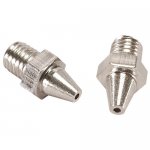
Desolder Iron back then $ 8.99 and a pack of 2 replacement tips, since they wear out $ 1.99

Now, you can get the original Radio Shack Desolder Iron as NOS on eBay / Amazon for $25.00 and a pair of replacement tips cost anywhere from $ 9.99 and up on the internet.......

It's 17:14 Hours here in Kansas and I got my feet up on my lazyboy and I am not running up to the shop either - has been a busy week -
Pictures I found via google of aforementioned parts......

rsdsi.jpg372-230_HR_0.jpg
 
Top
AdBlock Detected

We get it, advertisements are annoying!

Sure, ad-blocking software does a great job at blocking ads, but it also blocks useful features of our website like our supporting vendors. Their ads help keep Steel Soldiers going. Please consider disabling your ad blockers for the site. Thanks!

I've Disabled AdBlock
No Thanks