• Steel Soldiers now has a few new forums, read more about it at: New Munitions Forums!

  • Microsoft MSN, Live, Hotmail, Outlook email users may not be receiving emails. We are working to resolve this issue. Please add support@steelsoldiers.com to your trusted contacts.

MEP-004a single phase rewire and SX460 conversion.

shackwrrr

New member
3
0
1
Location
piedmont, oh
Had a friend drop off his 004 for me to diag and fix, he had it at a generator shop for 6 months and all they did was unplug and remove the special relay box. I removed the regulator/exciter and found T2 completely fried and the inside of the box charred from the internal fire. After failed searching for a regulator and lots of research I have broken down the diagram enough to hook up a SX460 regulator for a cheaper fix. Since the SX460 is a 220/110 regulator we decided to rewire the generator into a zig zag config. I have broken down the diagram enough to find the 2 wires that feed 208v now(220 after the zigzag), 2 wires to the field, and 2 wires from the field flash relay. The voltage feed and field wires are easy and will transfer over to the new reg easy, the difficulty starts with the field flash. In the factory regulator the field flash wires are tied directly to the field wires (feeding 24v when the speed switch and start switch allow). My question is, will the 460 tolerate 24v applied to the field circuit before it starts outputting its own power? Or do I need some sort of protection like a diode or relay to break contact? In the instructions it mentions removing the field wires from the regulator before flashing the field, this is why I am asking.


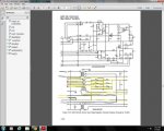
Here is my diagram where I have broken down the wires going into the exciter/regulator box.
regulator.jpg

The wires with the red dots are from one of the current transformers, I assume that this is so the regulator can keep an eye on the load. These are not needed with the 460.

The black wires on L and M are the 208 feed, these originally fed the regulator with power so It could do its thing, you can see these feed directly into T2, the transformer that was fried on mine. After the conversion, these 2 pins will be the 220v input to the regulator to sense voltage output.

The yellow wires are the F1 and F2 wires, These go directly to the field coil on the genset, they will serve the same purpose with the new reg.

The blue wires are the 24v feed from the field flash relay, if you follow the blue lines you can see where these wires are directly connected to the field wires, this is the reason for my post.

The last 3 wires are mostly unused, T just remains a ground, and B-A on J9 were the original 110v sense wires for the regulator. (original regulator set a goal of 110v per phase, 208v was just a byproduct of phase overlap.) Since the new regulator has a goal of 220 total, these pins are not used. (I will lose parallel unit operation, fine voltage adjustment, and remote control functions due to this). I could however set up the SX460 to read 110v and keep these, but using the 220v input seems more accurate.

Any input on my conversion idea is appreciated.
 

Triple Jim

Well-known member
1,375
287
83
Location
North Carolina
In the instructions it mentions removing the field wires from the regulator before flashing the field, this is why I am asking.
Not trying to be a smart-ass, but this means you need to remove the connection between the regulator and field before flashing the field. Diode isolation would be an option.

If you have any questions, I'd recommend asking the manufacturer of the regulator.
 
Last edited:

Isaac-1

Well-known member
1,970
50
48
Location
SW, Louisiana
You might also try seeing if it works (reliably) with the flash circuit removed, I suspect the SX-460 will build output with a much smaller residual voltage than the original AVR
 

shackwrrr

New member
3
0
1
Location
piedmont, oh
Not trying to be a smart-ass, but this means you need to remove the connection between the regulator and field before flashing the field. Diode isolation would be an option.

If you have any questions, I'd recommend asking the manufacturer of the regulator.
Well the instructions(found here: http://www.dieselgeneratorsmiami.com/recursos_tecnicos/NEWAGE-SX460-AUTOMATIC-VOLTAGE-REGULATOR.PDF) Make mention of disconnecting the field wires but I don't know if it's to save the regulator, or just to free up the wires to use a current limiting resistor and a battery. The unit I bought is a copy so emailing the manufacturer in china probably is not an option.

1. With the Prime-mover at rest and the regulator’sfield output wires disconnected, apply a DC
source ( NOT grounded ) of not more than 3~12
Vdc with Positive to F+ and Negative to F-, in
series with a current-limiting resistor of 3~5 ohms
20 watt. (The set battery is a suitable source.)
2. Allow approximately 3 seconds before removing
the DC source.
3. With the voltage regulator disconnected ( wires 3
and 4 ), start the prime mover and measure the
“ residual ” voltage available at the auxiliary
winding. If this voltage is greater than 5 Vac,
reconnect voltage regulator, and voltage build-up
should be successful. If less than 5 Vac is
measured, repeat field flashing procedure.
4. If repeating steps a. and b. does not result in
generator voltage build-up, and residual is
greater than 5 Vac, replace voltage regulator.
 

Triple Jim

Well-known member
1,375
287
83
Location
North Carolina
It says that those flashing instructions are for the first time the new regulator is used with the generator, if there is not enough residual magnetism to get things started.

I've emailed Chinese manufacturers and received useful responses before, when I was working with Chinese CDI units. Don't be too sure they won't help if you have a question the instructions don't answer.
 

glassk

Active member
998
6
38
Location
Hampton, GA
In the instructions it mentions removing the field wires from the regulator before flashing the field, this is why I am asking.

----it reads to me you do that step to check if flashing is needed,
2cents
start the prime mover and measure the
“ residual ” voltage available at the auxiliary
winding. If this voltage is greater than 5 Vac,
reconnect voltage regulator, and voltage build-up
should be successful.
 

shackwrrr

New member
3
0
1
Location
piedmont, oh
I finally found out about hooking up the field flash, I found some wiring diagrams that showed a diode inline on the field flash wiring.

I have found why the original regulator went though, after frying a regulator I went through all of my wiring and found that my field coil is only 2.5 ohms. Sounds like I have some internal issues.
 

SLTRAM98

New member
27
23
3
Location
North Carolina
Good afternoon,
I am working with a MEP-005a, trying to install the SX460 for the Voltage Regulator but not sure what other items from the Static Exciter portion of A11 should be removed. The generator is currently setup for 120/208 3-phase. Just looking to see what you ended up doing on yours? My gen has the same wire diagram as yours. I have posted pictures at this posts (https://www.steelsoldiers.com/threa...rket-avr-on-mep004a-005a.210642/#post-2469652) and would like some input if you are able.

Thank you!
 

Ray70

Well-known member
2,592
5,904
113
Location
West greenwich/RI
Humm.... SX460 on an 004/005 Eh?
I've never tried it on that size machine, only the 3Kw machines, but I thought I read here on SS that the SX460 could not be used on those machines?
Don't recall the exact reason, but think maybe it couldn't supply enough current possibly??
I remember RustyStud converted an 002 years ago, but IS there an issue using the SX460 on an 004/005??
Anyone rememer?
 

SLTRAM98

New member
27
23
3
Location
North Carolina
Hello Ray70, Thanks for the reply, From my research, the issue arises from the initial flash required when installing the SX460 and removing the A11. From my reading, if you have 5vdc-'ish' at the poles in residual power, you can flash it. I know some folks on here add a push button to make a flash contactor to get it started. I 'think' part of the issue with the flash is the removal of ALL the internal components from the static exciter system inside A11. Of all the transformers and rectifiers, somewhere inside A11 there MUST be an acting initial flash exciter when the system was working normally from the start switch (again, someone point me in a better direction if you know). From my research (open to input, thats why I ask), the SX460 will easily regulate the power once initial flash is done. My thoughts are to pull 120volt monitor power from the secondary poles of T2 inside A11 - basically this is exactly what the old Voltage Regulator (VR) was looking at (I think); then, connect F1 and F2 of the SX460 to J13 wires R & S (TB16-2 & TB16-1). This leaves all the other components inside A11 and replaces the VR board only - thoughts??!?!!

Looking for all the help I can get, just need some nudging by someone savy in these. Thank you
 

kloppk

Well-known member
Steel Soldiers Supporter
2,145
3,526
113
Location
Pepperell, Massachusetts
I think your S.O.L. trying to use the 460 in your 005.
The 460 is rated for use with exciters that are 15 ohms or greater.
The 005's exciter is 5.0 ohms.
If the 460 was used the 460 would likely go up in smoke trying to drive a 5 ohm load.
 
Top
AdBlock Detected

We get it, advertisements are annoying!

Sure, ad-blocking software does a great job at blocking ads, but it also blocks useful features of our website like our supporting vendors. Their ads help keep Steel Soldiers going. Please consider disabling your ad blockers for the site. Thanks!

I've Disabled AdBlock
No Thanks