deuce bigalow
New member
- 18
- 0
- 0
- Location
- the islands
Ok so the frequency issue was caused by incorrect rpm, I got that dialed in now.
I was able to run a drill motor off the convenience receptacle.
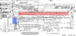
The circuit breaker indicator will not illuminate when I hold the circuit breaker switch up, but it lights up when I push the light in to test it. So the indicator is good but mabey the switch or the breaker is bad?
I tried hitting the test/reset to reset the reverse power indicator but it didn't work. The reverse power indicator will go off temporarily if I hold the start switch up while running.
I was able to run a drill motor off the convenience receptacle.
The circuit breaker indicator will not illuminate when I hold the circuit breaker switch up, but it lights up when I push the light in to test it. So the indicator is good but mabey the switch or the breaker is bad?
I tried hitting the test/reset to reset the reverse power indicator but it didn't work. The reverse power indicator will go off temporarily if I hold the start switch up while running.