• Steel Soldiers now has a few new forums, read more about it at: New Munitions Forums!

  • Microsoft MSN, Live, Hotmail, Outlook email users may not be receiving emails. We are working to resolve this issue. Please add support@steelsoldiers.com to your trusted contacts.

MEP-005a Generator not putting out any power

M35A2-AZ

Well-known member
Steel Soldiers Supporter
3,222
392
83
Location
Tonopah, AZ
I got my Mep-005a motor running after getting the pump rebuilt.
But now the generator side is not working. The gages on the panel show no voltage or Hz.
Is there something I need to do to get the generator to start working?
 
Last edited:

leedawg

Member
270
10
18
Location
Napa / CA
So as I mentioned before you need to flash the field. So start it up again and then hold the switch in the start position for about 10 seconds after it comes up to rpm. Then release it and you should start seeing power being generated. Again avoid idling it just throttle it right up to speed. Let us know how it goes if it still does not put out power your going to have to start tracking down where the problem is. My guess would be the voltage regulator and the dc power being put out to the gen head for the field strength.

Lee
 

M35A2-AZ

Well-known member
Steel Soldiers Supporter
3,222
392
83
Location
Tonopah, AZ
lee, again thank you!!!! I am going to need to buy you dinner!!!
I feel so dumb sometime. That did get the field to working and the generator started showing voltage and Hz. Also ran a drill motor out of the 110v outlet.

But I do have one more question, Should the generator automatically come up to speed? The only way it comes up to speed is for me to pull out the Manual speed control, but it does not lock into place.
 

leedawg

Member
270
10
18
Location
Napa / CA
No worries um figures star with the easy things first. I glad that fixes it for ya. As far as the throttle goes yes you have to manually set it to sixty hz it should stay at where you set it at. It's a twist throttle you spin it counter clockwise and it should speed up as the throttle cones out more and clockwise goes slower.... Gonna be watching the game so be on later.... Go Niners!!
 

M35A2-AZ

Well-known member
Steel Soldiers Supporter
3,222
392
83
Location
Tonopah, AZ
Lee, Thanks, I looked the throttle again and I must be missing a part or its broken.
I can pull all black parts out to increase the power but that is the only way I can see to do it.
 

leedawg

Member
270
10
18
Location
Napa / CA
Sorry for the slow response.

Sunday night was a tough loss for me :( But we wont get into that right now however I still think we should have won that game...

We will be back though!!

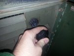
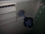
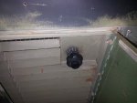
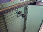
Any way I took the liberty of taking a few pictures of the throttle so you could see what a normal operating one looks like and how it should work.
So this first picture here (the one all the way on the right down below for some reason inline did not work) shows the throttle in the closed position or otherwise all the way in (Hz are going to be very low in this position avoid running here you will possibly burn up your voltage regulator!)


SO this second picture (middle picture) shows mine with the thorttle at about 60 hz for my unit. TO get it there just push the button in and pull it out or if you feel like taking the long way to getting there just keep twisting it in a CCW fashion till it is extended out to about this position. One thing to note notice that ring with the lines on it where the throttle bar comes out of the side wall of the generator. If you twist that to the CC direction it will tighten up the friction setting on the throttle so that if its not holding its position very well it will hold better if you tighten up that friction nut.


And this (the one on the left) picture is just simply showing you pushing the button in as you move the throttle in or out. Pretty easy cheesy.
 

Attachments

Last edited:

M35A2-AZ

Well-known member
Steel Soldiers Supporter
3,222
392
83
Location
Tonopah, AZ
Lee, Thanks for the pics!!!
I think my thorttle my be broken, it does not work that.
I have to pull the complete unit out to get it to move.

Thanks for all your help!!!
 

edgephoto

Member
133
1
18
Location
Stafford, CT
Lee, Thanks for the pics!!!
I think my thorttle my be broken, it does not work that.
I have to pull the complete unit out to get it to move.

Thanks for all your help!!!
There is a generic throttle cable that works on the 002 and 003 units. If you do a search you should find a post with brand and part number. Then you can compare specs and see if it will work.
 

M35A2-AZ

Well-known member
Steel Soldiers Supporter
3,222
392
83
Location
Tonopah, AZ
Sorry for the slow response.

Sunday night was a tough loss for me :( But we wont get into that right now however I still think we should have won that game...

We will be back though!!

Any way I took the liberty of taking a few pictures of the throttle so you could see what a normal operating one looks like and how it should work.
So this first picture here (the one all the way on the right down below for some reason inline did not work) shows the throttle in the closed position or otherwise all the way in (Hz are going to be very low in this position avoid running here you will possibly burn up your voltage regulator!)


SO this second picture (middle picture) shows mine with the thorttle at about 60 hz for my unit. TO get it there just push the button in and pull it out or if you feel like taking the long way to getting there just keep twisting it in a CCW fashion till it is extended out to about this position. One thing to note notice that ring with the lines on it where the throttle bar comes out of the side wall of the generator. If you twist that to the CC direction it will tighten up the friction setting on the throttle so that if its not holding its position very well it will hold better if you tighten up that friction nut.


And this (the one on the left) picture is just simply showing you pushing the button in as you move the throttle in or out. Pretty easy cheesy.
Lee, I got a new throttle cable and now it works great!!! I old cable was broken in side I guess.
Thanks again for all your help!!
 

Attachments

Reddsta

New member
1
0
0
Location
Madison, Wi.
I am not sure if anyone can hear me...but here goes

MEP-005A after starting I cannot excite because the starter is engaging. Any ideas?

Thanks Red
 

leedawg

Member
270
10
18
Location
Napa / CA
Wow resurrected this thread from the grave.

Well as far as not being able to excite the field due to the stater engaging after the set is running makes me think there is clearly a problem with your engine speed lock out switch. So if ya look on the left side of the engine you will see this large round canister looking thing that sticks Into the crankcase of the motor. There is a cannon plug on the top of it with a bunch of wires going Into it. This controls three things it shuts the set down if the engine over speeds, it also locks out the starter when the engine is running and I think it also allows you to flash the feild when the engine is up to speed if memory serves correct. You might have to crack it open and see if there is a problem with the microswitchs inside. I wrote up a post on this about a year ago with pictures. If you have the electronic speed switch then disregard all this gonna need an oscilloscope and some good bench electronics diagnosing skills to figure out what's wrong with it. Id just source a new one at that point.

Here is the post
https://www.steelsoldiers.com/showt...tch-tear-down-and-repair-(mechanical-version)
 

Guyfang

Moderator
Staff member
Moderator
16,777
24,105
113
Location
Burgkunstadt, Germany
If it's an old style mech switch, often it's just a wire broken off at the micro switch. The S9-1 contacts have to be closed to start the gen set. At the spec. RPM, the S9-1 opens, shutting off the starter and at the same time closes contacts to light off the static Excitor. The S9-2 contacts are not used. S9-3 shuts off power to the L4 IP solinoid, to kill the engine if it over speeds. It is possible to replace the S9-1 switch with S9-2, to make a good switch. Mark the adjusting screws BEFORE taking the switch apart, or you might have to figure out where the settings are, if you have the right gear. Variable speed mother to drive the switch, timing light, (or something else similar) to find the trip points. This info is all in the -34 TM. In any case, read the book before fooling with it.

Now, to the part about buying one. You need to be careful what you buy. There are about 15 different S9 switches you can buy. The reason that is so, is because they were not real good quality. Not all are the right type, and I don't care what the seller tells you. Someplace in the forum is a list I posted, and listed the newest version part number/NSN.
 

Jimmie Morgan

Member
62
12
8
Location
Goodman, Missouri USA
I have a MEP 005A 1977 Model. Has been sitting for over 10 years. I have it running good with a Jumper wire to the Engine injector pump. When I turn on the Stop run start switch it does not give any power to the Fuel Pumps or the Injection pump. After I get it running I can push up on the START switch & it will make Electricity. As soon as I let off of it the Current Quits. Anyone have any Ideas without me having to do a BUNCH of checking? Thanks BTW I am 74 years old & cannot fix things like the old days !!!! LOL
 

Guyfang

Moderator
Staff member
Moderator
16,777
24,105
113
Location
Burgkunstadt, Germany
Jimmie,

Please start your own thread, as it makes it hard for people to help you, and the person who started this thread. If you need help doing so, tell me and I will help you walk though it. And I promise someone will jump right in to help you!!
 
Top
AdBlock Detected

We get it, advertisements are annoying!

Sure, ad-blocking software does a great job at blocking ads, but it also blocks useful features of our website like our supporting vendors. Their ads help keep Steel Soldiers going. Please consider disabling your ad blockers for the site. Thanks!

I've Disabled AdBlock
No Thanks