• Steel Soldiers now has a few new forums, read more about it at: New Munitions Forums!

  • Microsoft MSN, Live, Hotmail, Outlook email users may not be receiving emails. We are working to resolve this issue. Please add support@steelsoldiers.com to your trusted contacts.

MEP 006A low oil pressure light / won't generate power

jeff22

New member
8
6
3
Location
Bulverde, TX
Hello, looking for help troubleshooting and fixing a MEP 006A that quit generating power.

We can get the diesel engine to start, and the oil pressure gauge reads about 50psi. But the Low Oil Pressure fault light is on, and it won’t generate power. We had this generator working just a few weeks ago.

Steps I have already taken to troubleshoot:
– I have changed the oil and both oil filters, twice.
– I have changed the oil pressure sending unit, didn’t make a difference.

Is there something I am missing? Something else to replace or clean?

Thank you for your help!
 

Guyfang

Moderator
Staff member
Moderator
16,789
24,135
113
Location
Burgkunstadt, Germany
Let me ask these questions.

As soon as you start the set up, does the LOP light come right on? Or does it come on when you try and close the S5, (AC power out) switch? And have you tried to start the set, get it running, and then flip up the S7, (Battle short ) switch, and then try and turn on the S5 and get power? Because if the LOP comes on, the set should shut down.


b. Stopping by Safety Devices. The engine generator
set is equipped with safety device electrical
circuits that will automatically stop the engine and
simultaneously open the main ac contactor in case
of; (1) high coolant temperature, (2) low oil pressure,
(3) engine overspeed, (4) over-voltage or, (5) no fuel.
A short circuit, overload, or reverse power protective
relay will automatically open the main ac contactor
but will not stop the engine.

So if the engine is not stopping, this could be one of several problems.
 

jeff22

New member
8
6
3
Location
Bulverde, TX
Did you check the low oil pressure switch?

The low oil pressure light doesn't get its signal from the sending unit but from a separate switch.
No I had not checked the low oil pressure switch. I somehow missed that in the TM. Thank you!

I believe the low oil pressure switch is my issue. Does anyone know where to source a new low oil pressure switch?
 

jeff22

New member
8
6
3
Location
Bulverde, TX
Let me ask these questions.

As soon as you start the set up, does the LOP light come right on? Or does it come on when you try and close the S5, (AC power out) switch? And have you tried to start the set, get it running, and then flip up the S7, (Battle short ) switch, and then try and turn on the S5 and get power? Because if the LOP comes on, the set should shut down.


b. Stopping by Safety Devices. The engine generator
set is equipped with safety device electrical
circuits that will automatically stop the engine and
simultaneously open the main ac contactor in case
of; (1) high coolant temperature, (2) low oil pressure,
(3) engine overspeed, (4) over-voltage or, (5) no fuel.
A short circuit, overload, or reverse power protective
relay will automatically open the main ac contactor
but will not stop the engine.

So if the engine is not stopping, this could be one of several problems.
The LOP light comes on right away when we start the set up.

Yes I have tried the procedure of starting the set, getting it running, then flipping the S7 (battle short) switch and then the S5.

The LOP light stays on, but the set stays running. I am able to "reset" the fault lights, which turns off the LOP light. But that doesn't make any difference when trying to close the S5 and turning power on.

Thank you for your help on this
 

jeff22

New member
8
6
3
Location
Bulverde, TX
The set should not stay running when you have a LOP situation. And if you can reset the LOP light, and it stays off, this is not normal also. Instead of buying a LOP switch, try testing it. Then try jumping the switch, to see if your set runs right.
Thank you for your help on this.

I took off the low oil pressure safety switch and it was visibly damaged. I have replaced the low oil pressure safety switch and was hopeful that would solve the issue.

Now with the new LOP safety switch installed, the low oil pressure fault light isn't on anymore, but now none of the fault lights turn on at all, even when hitting the test switch. I checked the fuse on the fault light panel, it seemed fine. I replaced the fuse just incase. Still no fault lights come on. And the diesel motor starts, but the generator won't turn on when try to close the circuit switch.

Is there another fuse somewhere that may have blown? What else should I be checking?
 

Guyfang

Moderator
Staff member
Moderator
16,789
24,135
113
Location
Burgkunstadt, Germany
I took off the low oil pressure safety switch and it was visibly damaged. I have replaced the low oil pressure safety switch and was hopeful that would solve the issue.

Now with the new LOP safety switch installed, the low oil pressure fault light isn't on anymore, but now none of the fault lights turn on at all, even when hitting the test switch. I checked the fuse on the fault light panel, it seemed fine. (What means, "Seemed fine"? Its a fuse. Did you test it with a multimeter? Did you test your replacment fuse before putting it in? And yes, you wold not be the first to put a bad fuse in. I have done it more then once in my life. ALWAYS test first) I replaced the fuse just in case. Still no fault lights come on. And the diesel motor starts, but the generator won't turn on (This means no output? The main gen is not turned on or off. It is suposed to produce voltage as soon as the engine comes up to rated speed. What is on the AC meter, on the control panel? What are you getting on the input side of the CB2? (output contactor) when try to close the circuit switch.

Is there another fuse somewhere that may have blown?

No, there is not. Place the S2 in the run position, and the CB1 in the on position. Then take the canon plug off the Fault Indicator. and test for 24 VDC on pin A of C-plug. That should be the 24 VDC positive pin, to the fault indicator. No voltage there, the Fault Indicator will not work.


What else should I be checking?

Thats all you did. Just changed the LOP, Nothing else?
 

jeff22

New member
8
6
3
Location
Bulverde, TX
I took off the low oil pressure safety switch and it was visibly damaged. I have replaced the low oil pressure safety switch and was hopeful that would solve the issue.

Now with the new LOP safety switch installed, the low oil pressure fault light isn't on anymore, but now none of the fault lights turn on at all, even when hitting the test switch. I checked the fuse on the fault light panel, it seemed fine. (What means, "Seemed fine"? Its a fuse. Did you test it with a multimeter? Did you test your replacment fuse before putting it in? And yes, you wold not be the first to put a bad fuse in. I have done it more then once in my life. ALWAYS test first) I replaced the fuse just in case. Still no fault lights come on. And the diesel motor starts, but the generator won't turn on (This means no output? The main gen is not turned on or off. It is suposed to produce voltage as soon as the engine comes up to rated speed. What is on the AC meter, on the control panel? What are you getting on the input side of the CB2? (output contactor) when try to close the circuit switch.

Is there another fuse somewhere that may have blown?

No, there is not. Place the S2 in the run position, and the CB1 in the on position. Then take the canon plug off the Fault Indicator. and test for 24 VDC on pin A of C-plug. That should be the 24 VDC positive pin, to the fault indicator. No voltage there, the Fault Indicator will not work.


What else should I be checking?

Thats all you did. Just changed the LOP, Nothing else?
Thank you for your help.

I have test the fuse with a multimeter and verified that the fuse is good.

"It is suposed to produce voltage as soon as the engine comes up to rated speed."

This generator isn't operating that way, and even when it was producing power, it did not operate that way. We have always had to start the diesel engine first with the S2 switch and then flip the S3 switch to CKT BRK CLOSE to produce power from the generator.

"What is on the AC meter, on the control panel?"

The VOLTS AC gauge on the control panel reads 0. Same for the PERCENT RATED CURRENT and PERCENT POWER gauges, both stay at 0.

"Place the S2 in the run position, and the CB1 in the on position. Then take the canon plug off the Fault Indicator. and test for 24 VDC on pin A of C-plug. That should be the 24 VDC positive pin, to the fault indicator. No voltage there, the Fault Indicator will not work."

With the S2 in run position and CB1 in on position, I do not get 24 VDC on pin A of the canon plug.

"What are you getting on the input side of the CB2?"

How/what would I do to test that with my meter?
 

Guyfang

Moderator
Staff member
Moderator
16,789
24,135
113
Location
Burgkunstadt, Germany
I have test the fuse with a multimeter and verified that the fuse is good.

"It is suposed to produce voltage as soon as the engine comes up to rated speed."

This generator isn't operating that way, and even when it was producing power, it did not operate that way. We have always had to start the diesel engine first with the S2 switch and then flip the S3 switch to CKT BRK CLOSE to produce power from the generator. (You dont understand. As soon as the gen set starts, and runs, it is making power. Always. When you flip S3 up, it closes the CB2, and you get power to the output lugs. You should ALWAYS get 120 volts to the 120 outlet, unles its CB is not closed or broken. )

"What is on the AC meter, on the control panel?"

The VOLTS AC gauge on the control panel reads 0. (There is a chance that the A2, Frequency converter is not working. Start the set up and measure for 120 VAC on the input side of the A2, The A2 is in the control cube. Its marked A2. If I remember right, the AC input side is on the left side of the A2. Wire #X12E goes to terminal 1. Wire #X9G goes to terminal 2.) Same for the PERCENT RATED (This should read 0, as long as there is no load on the set, so its normal.) CURRENT and PERCENT POWER gauges, both stay at 0. (This also should read 0, as long as there is no load on the set, so its normal.)

"Place the S2 in the run position, and the CB1 in the on position. Then take the canon plug off the Fault Indicator. and test for 24 VDC on pin A of C-plug. That should be the 24 VDC positive pin, to the fault indicator. No voltage there, the Fault Indicator will not work."

With the S2 in run position and CB1 in on position, I do not get 24 VDC on pin A of the canon plug.

"What are you getting on the input side of the CB2?"

How/what would I do to test that with my meter?

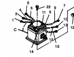
The CB2 is the Output contactor. Looks like this. It is on the left side, rear door.1679348616795.png
The left side is the input. If the cover is on it, remove the left cover, start the set and measure from ground to each wire there. Its just 3, the 3 phases. You should get 120VAC to each terminal. What do you get?
 

jeff22

New member
8
6
3
Location
Bulverde, TX
You dont understand. As soon as the gen set starts, and runs, it is making power. Always. When you flip S3 up, it closes the CB2, and you get power to the output lugs. You should ALWAYS get 120 volts to the 120 outlet, unles its CB is not closed or broken.
Ah ok, that makes much more sense. So I tested the 120 volt outlet that is on the side of the case, with the gen set running I do not get power to that outlet. I tried pulling out and pushing in the small CB that is just below the outlet. That did not make a difference. So does that 120 outlet make power even if the S3 has not been flipped up and the CB2 hasn't been closed?

There is a chance that the A2, Frequency converter is not working. Start the set up and measure for 120 VAC on the input side of the A2, The A2 is in the control cube. Its marked A2. If I remember right, the AC input side is on the left side of the A2. Wire #X12E goes to terminal 1. Wire #X9G goes to terminal 2.) Same for the PERCENT RATED (This should read 0, as long as there is no load on the set, so its normal.) CURRENT and PERCENT POWER gauges, both stay at 0. (This also should read 0, as long as there is no load on the set, so its normal.)
I followed your instructions to test the A2 Frequency converter. With the set running I was not able to measure any voltage on the input side of the A2. Although I may not be using the leads on my multimeter correct to test. Testing using a multimeter is admittedly not my strength but I have watched a few YouTube videos to brush up on the basics. So to test for 120 VAC on the input side, I should be putting the red test lead on to one of the terminals and the black test lead to a good ground, correct?

Also, I noticed that my wire #X12E goes to terminal 2 and wire #X9G goes to terminal 1. Those wires have not been messed with and look to be in the place they have always been. Not sure if that is an issue.

The CB2 is the Output contactor. Looks like this. It is on the left side, rear door.View attachment 893684
The left side is the input. If the cover is on it, remove the left cover, start the set and measure from ground to each wire there. Its just 3, the 3 phases. You should get 120VAC to each terminal. What do you get?
Ok, I found the CB2 output contactor. I used my multimeter to test for 120VAC on each of the three lugs on the left side. I got 0 VAC on all three.

Could the problem be as simple as the S3 switch being bad? How would I test the S3 switch to rule that out?

Once again, I appreciate all your help. Once I get this up and running I owe you one!
 

Ray70

Well-known member
2,598
5,925
113
Location
West greenwich/RI
S3 would not be causing your problem. As mentioned, the generator SHOULD be producing power whenever the engine is running. That power should always be present at the AC outlet ( assuming it's CB is good ) it will also always be present on the input wires of the contactor.
You don't have power in either location, therefore it is safe to assume that the generator is not producing power for 1 reason or another.
Guyfang is the master of the 004/005 and 006 ( among other things ) he will guide you down the road to success!
 

Guyfang

Moderator
Staff member
Moderator
16,789
24,135
113
Location
Burgkunstadt, Germany
Ray wrote:
S3 would not be causing your problem. (Correct) As mentioned, the generator SHOULD be producing power whenever the engine is running. That power should always be present at the AC outlet ( assuming it's CB is good ) it will also always be present on the input wires of the contactor. (This is what I wanted you to check, and you did. All the places I asked you to check. are places to see if the set is making power, but for some reason, (A2, CB2, J55 and Ect))
You don't have power in either location, therefore it is safe to assume that the generator is not producing power for 1 reason or another.

What kind of S9 switch, (Over speed switch) do you have? Old style, with three screw on it to adjust it? Or an electronic S9?

Have you taken the Special relay box out/apart lately? Are all the canon plugs tight?

Find TB16 on the left side, rear door. Should be marked as TB16. Have someone start the set, while you measure at pins TB16-15 and TB16-16 for 24 VDC, while the engine is cranking and running. What do you get?
 

jeff22

New member
8
6
3
Location
Bulverde, TX
What kind of S9 switch, (Over speed switch) do you have? Old style, with three screw on it to adjust it? Or an electronic S9?
I have the old style over speed switch with the three screws to adjust it.

I followed the troubleshooting instructions listed in the technical manual and tested the over speed switch for continuity between pins A and B, G and H. I believe the overspeed switch is good based on that test. Not sure if it needs to be adjusted though.


Have you taken the Special relay box out/apart lately? Are all the canon plugs tight?
I doubled checked all of the canon plugs to verify they are all tight. No we have not taken out or opened the special relay box.


Find TB16 on the left side, rear door. Should be marked as TB16. Have someone start the set, while you measure at pins TB16-15 and TB16-16 for 24 VDC, while the engine is cranking and running. What do you get?
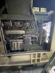
I'm having trouble finding TB16.

IMG_6026.jpg

It is inside this door? I see TB6 but not TB16.

Also, I checked for continuity across A1 and A2, B1 and B2, C1 and C2 on CB2. I was able to confirm continuity on B1 and B2, C1 and C2... but A1 and A2 do. not have continuity.
 

Guyfang

Moderator
Staff member
Moderator
16,789
24,135
113
Location
Burgkunstadt, Germany
I have the old style over speed switch with the three screws to adjust it.

I followed the troubleshooting instructions listed in the technical manual and tested the over speed switch for continuity between pins A and B, G and H. I believe the overspeed switch is good based on that test. Not sure if it needs to be adjusted though.
I dont think so. I never ever had to adjust one. They work, or not.

Below is whats important. The field flash part. At 300 RPM the A&B should open, and A & C should close. Thats the field flash. I cant copy the whole passage. Look at the -34 TM.


1680033982043.png
b. At an engine speed of 580 to 620 rpm (accelerating)
element S9–1 transfers two sets of contacts,
energizing the field flash circuit and de-energizing the
crank relay to stop the starting motor.


I doubled checked all of the canon plugs to verify they are all tight. No we have not taken out or opened the special relay box.


I'm having trouble finding TB16.

View attachment 894058

It is inside this door? I see TB6 but not TB16.

TB6 should be the reconnection board. Make sure its in the right position. TB16 should be the small TB, to the upper right. TB16-15 and TB16-16 should be the last two wires on the right side, if I remember right. Its only been 13-14 years since I looked at one.

Also, I checked for continuity across A1 and A2, B1 and B2, C1 and C2 on CB2. I was able to confirm continuity on B1 and B2, C1 and C2... but A1 and A2 do. not have continuity.

When the set is running, and the CB is closed?
 

jeff22

New member
8
6
3
Location
Bulverde, TX
TB6 should be the reconnection board. Make sure its in the right position. TB16 should be the small TB, to the upper right. TB16-15 and TB16-16 should be the last two wires on the right side, if I remember right. Its only been 13-14 years since I looked at one.
Ah ok, I found TB16 and found the two wires, TB16-15 and TB16-16. I had someone start the set while measuring at the TB16-15 and TB16-16 pins for 24 VDC. I measured 0 VDC while cranking and while the engine was running.


Also, I checked for continuity across A1 and A2, B1 and B2, C1 and C2 on CB2. I was able to confirm continuity on B1 and B2, C1 and C2... but A1 and A2 do. not have continuity.

When the set is running, and the CB is closed?
No, that was with the set off.

I have checked it again for continuity with the set running and the CB2 closed. I do get continuity across A1 - A2, B1 - B2, and C1 - C2.

Any ideas on what could be causing the problem?
 

Guyfang

Moderator
Staff member
Moderator
16,789
24,135
113
Location
Burgkunstadt, Germany
You are getting no excitation voltage to the main gen. The initial excitation voltage is sent from the S9 switch.

b. At an engine speed of 580 to 620 rpm (accelerating)
element S9–1 transfers two sets of contacts,
energizing the field flash circuit and de-energizing the
crank relay to stop the starting motor.

This information is on PDF page #329, of the -34 TM. You need to check the S9 for proper operation.
 
Top
AdBlock Detected

We get it, advertisements are annoying!

Sure, ad-blocking software does a great job at blocking ads, but it also blocks useful features of our website like our supporting vendors. Their ads help keep Steel Soldiers going. Please consider disabling your ad blockers for the site. Thanks!

I've Disabled AdBlock
No Thanks