• Steel Soldiers now has a few new forums, read more about it at: New Munitions Forums!

  • Microsoft MSN, Live, Hotmail, Outlook email users may not be receiving emails. We are working to resolve this issue. Please add support@steelsoldiers.com to your trusted contacts.

Mep 006A won't turn over

Powermaker16

New member
18
4
3
Location
Charleston, SC
Post #38 tells us you can not get the CB2 to close. Not even in Battle short. The reason you get sparks on the left side is because the gen set makes voltage, but it will not go any farther because CB2 will not close. So I would take the canon plug off the CB2 and CAREFULLY apply 24 volts to pin A&B of the CB2. Will it clunk? No NOT perform this test while the set is running.
The Generator was not running when I tried the test and still got sparks. Again, I was trying to confirm the A1, and B1 which are the top left two posts on the CB2 are what you are talking about. You mentioned "pins." I have tried to read the TM -12 manual and even the page 3-71 that says put 24v to pins A and B, but there is no illustration. Looking at wiring diagrams, there are A's and B's all over the place. I am lost here. I am about to just put a jumper wire to the other side of CB2 and call it a day. :-(
 

Guyfang

Moderator
Staff member
Moderator
17,391
25,703
113
Location
Burgkunstadt, Germany
Left side, top two LARGE wire connections A1 & B1. see attached crude drawing. Also, the blue tag on the side of CB2 has this drawing.

With everything turned off, unscrew the canon plug on the right side of CB2.
Move it out of the way.
Use a flashlight to look into the plug, on the CB2. Find pins A&B.
Carefully put the + positive on pin A
Carefully put the - negative on pin B
As the instructions below explain, it should make a noise, (Clunk)
If not then you can try and take CB2 apart and fix it
If it clunks, take a DMM and measure for continuity just like in the instructions below.
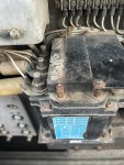

1742651504719.jpeg

apply 24 Vdc at pins A and B of main ac
contactor (3) connector. When main ac contactor
operates, it should create a distinctive noise.
(2) With an ohmmeter, check for continuity
between terminal Al to A2, B1 to B2, and Cl to
C2 on top of the main ac contactor.
(3) At the connector, check for continuity
b~tween pins C to D, E to F, G to H, J to K, and
R to T.
(4) At the connector, check for an open circuit
between pins L to M, N to P, and R to S.
(5) Remove the 24 Vdc and check for the opposite
of the conditions (continuity or open circuit)
listed in steps (2), (3), and (4).
 

Attachments

Top