• Steel Soldiers now has a few new forums, read more about it at: New Munitions Forums!

  • Microsoft MSN, Live, Hotmail, Outlook email users may not be receiving emails. We are working to resolve this issue. Please add support@steelsoldiers.com to your trusted contacts.

MEP-007B DC Relay Control Issue

SLTRAM98

New member
27
23
3
Location
North Carolina
Looking for some help on this one. I have a MEP-007B with the Cat 3306 engine 100kw generator. Has 1000 hrs on it.

Genset background:
- Has not been running in roughly 11 years.
- Was in use when it quit, the guys I got it from had no idea what was wrong with it.
- Barn stored after it quit.

Investigation and what I know:
- The genset has a full (100%) tank of diesel in it, but the day tank and engine fuel filter housing was bone dry. Implies to me that she was running, then something failed in the fuel call system and it ran out of fuel without ever shutting down on its own. Likely the guys thought it was out of fuel, filled it up and it would not run since the priming pumps would not cycle at all.
- When you cycle the start-run-stop switch to the run position, no fuel pumps turn on. The Low Oil Pressure light comes on 'sometimes', the over speed light also comes on 'sometimes'.
- Hit the over speed reset, and light does not go out, but if you toggle start-stop-run switch off and on a few times both lights come and go depending on the speed of the wind and angle of the sun.
- If you crank the engine it will not hit.
- I cleaned all the priming pumps (x2), pulled strainer baskets, pulled filters (1 strained, 2 filters) and jumped 24vDC to A27 panel board A5, CR6 diode. Pumps come on, float works perfectly, day tank fills, life is good.
- 1) I know both pumps are good and pump great.
- 2) I know the fuel day tank solenoid is working.
- 3) I know the float system works.
- 4) I know 100% I have gravity feed pressure from the day tank to the injection pump on the engine.
- 5) I cracked injector lines, and have fuel at injectors on the head of the engine.
- 6) Crank engine and it SMOKES, like it really wants to start, but cant, with the 24vDC bypassing shutdown safety's directly connected to the fuel system I am at a loss as to why it will not start since all the safety's (I think) are jumped in order to make pumps run. I have it sucking brand new diesel out of a 5 gallon jug and clean nice fuel at the injection pump.
- 7) I have replaced diodes CR27 and CR28, I know they are working.
- 8) I opened A27 relay Mode 1 box, the A5 circuit board is in great shape, but you can see Resistor R3 has been a bit warm, slight discoloration but nothing compared to other gensets I have worked on - not sure if this helps just a note.
- Strange note: If I turn ON Battle Short, the red light comes on, and the start-run-stop switch STOPS working at all, no cranking, no anything.
- I applied 24vdc to the fuel shut off solenoid on the injection pump and it works as expected. CLARIFY to check my sanity here, the solenoid is regularly OPEN, meaning NO voltage. Voltage applied means the solenoid activates and shuts down the engine, correct? EG if I apply 24vdc to the solenoid while cranking it has no fuel and will never start.
- Engine speed sensor - I ran it all the way in until it bottomed out on the flywheel, then backed it out 3/4 of a turn. Not sure how else to check this item. I read on a different thread to look for 10.5volts from this however, not sure where to actually check for that voltage.
- I applied 24vDC to K1 relay TB posts 8 on board A4 and this activities the fuel shut off solenoid and runs the priming pumps.
I have TM -12, -24 and luckily found -34 for this unit. Still after all day working on her, not sure what I am missing.

How does the speed governor control this engine is a question; since the engine smokes like its got loads of fuel, it seems something is keeping it from starting, however, its not a smart engine (no computers) so how is the Speed Governor actually wired/connected to the engine? Since the Over Speed light is on sometimes, I have a feeling something is a-miss in that department. I think Oil Pressure light is only on because the engine is off, if you crank it for a few seconds light seems to disappear for a bit then comes again. Also, any way to bypass speed governor to check it quickly?

I have attached the wire diagram to this thread. Circles are where I tested 24Vdc, yellow highlighted madness is where I 'think' I traced power routing. Square boxes are denoting some (not all) of the relays, boards, switches.

Let me know what you think guys, all ears and can get pictures. Thank you
 

Attachments

SLTRAM98

New member
27
23
3
Location
North Carolina
Update: Tore the injector pump down, found the rack was jammed closed, dug through and found that the plungers were broken/stuck (3 out of 6). New plungers coming, expect that will solve the engine starting problem when I bypass everything. Still need DC controls assistance. Thank you

PS will posts picture of the injector pump mess.
 

Guyfang

Moderator
Staff member
Moderator
16,777
24,103
113
Location
Burgkunstadt, Germany
Looking for some help on this one. I have a MEP-007B with the Cat 3306 engine 100kw generator. Has 1000 hrs on it.

Genset background:
- Has not been running in roughly 11 years.
- Was in use when it quit, the guys I got it from had no idea what was wrong with it.
- Barn stored after it quit.

Investigation and what I know:
- The genset has a full (100%) tank of diesel in it, but the day tank and engine fuel filter housing was bone dry.

(My first thought here was to tell you to check the 3 way fuel valve. But since you hot wired the A5, CR6 diode and the fuel pumps fill the day tank, I have to ask, is this from your 5 gal jug? Or the set tank? If the 3 way valve is in the off position, then, the E-pumps can not fill anything up. And yes, I have seen this a number of time, and had it happen to me several times. So, is the three way valve in the set position? You can also turn the 3 way valve to AUX, and run a line directly to the 5 gal jug, from the AUX inlet)

Implies to me that she was running, then something failed in the fuel call system and it ran out of fuel without ever shutting down on its own. Likely the guys thought it was out of fuel, filled it up and it would not run since the priming pumps would not cycle at all. (Possible)
- When you cycle the start-run-stop switch to the run position, no fuel pumps turn on. The Low Oil Pressure light comes on 'sometimes', the over speed light also comes on 'sometimes'.

(If you had access to another Fault Indicator, I would tell you that the SCR's in the Fault indicator do go bad, and often. This was a problem we had from the first time we saw a fault indicator, until the last time I saw one. I would not call it an age problem, because we saw this problem over the entire 30 years I fooled with this kind of system. The fault indicator's only function is to tell you that there was a fault. It will NOT shut anything down. It controls nothing other than the lights. )

- Hit the over speed reset, and light does not go out, but if you toggle start-stop-run switch off and on a few times both lights come and go depending on the speed of the wind and angle of the sun.

(Another reason I would suspect that the SCR's might be bad.)

- If you crank the engine it will not hit.

That tells me the problem could be in the Fuel Solenoid and the K1 contacts shown here. So, pull the wire off the fuel Solenoid and measure for 24 VDC at the wire while someone else turns the engine over.

1711486772386.png
If no voltage is at the Engine Fuel Solenoid wire, notice that the K1, on the A4 card, (inside the control panel) may not be working. That would be my first guess. Followed by S9-3 contacts.
1711487441523.png


- I cleaned all the priming pumps (x2), pulled strainer baskets, pulled filters (1 strained, 2 filters) and jumped 24vDC to A27 panel board A5, CR6 diode. Pumps come on, float works perfectly, day tank fills, life is good.
- 1) I know both pumps are good and pump great.
- 2) I know the fuel day tank solenoid is working.
- 3) I know the float system works.
- 4) I know 100% I have gravity feed pressure from the day tank to the injection pump on the engine.
- 5) I cracked injector lines, and have fuel at injectors on the head of the engine.
- 6) Crank engine and it SMOKES, like it really wants to start, but cant, with the 24vDC bypassing shutdown safety's directly connected to the fuel system I am at a loss as to why it will not start since all the safety's (I think) (How did you jump S9-3?) are jumped in order to make pumps run. I have it sucking brand new diesel out of a 5 gallon jug and clean nice fuel at the injection pump.
- 7) I have replaced diodes CR27 and CR28, I know they are working.
- 8) I opened A27 relay Mode 1 box, the A5 circuit board is in great shape, but you can see Resistor R3 has been a bit warm, slight discoloration but nothing compared to other gensets I have worked on - not sure if this helps just a note.

This is a known week spot. The A4 and A5 card)

- Strange note: If I turn ON Battle Short, (S7) the red light comes on, and the start-run-stop switch STOPS working at all, no cranking, no anything.

(This is normal. NO military gen set will start with the S7 in the on position)


- I applied 24vdc to the fuel shut off solenoid on the injection pump and it works as expected. CLARIFY to check my sanity here, the solenoid is regularly OPEN, meaning NO voltage. Voltage applied means the solenoid activates and shuts down the engine, correct? EG if I apply 24 VDC to the solenoid while cranking it has no fuel and will never start.

(Wrong. The solenoid is NORMALLY shut. You have to HAVE 24 VDC there for it to open and let fuel through. Otherwise, it would not be a saftey switch. Loss of power when the set over speeds would NOT stop the engine.)

- Engine speed sensor - I ran it all the way in until it bottomed out on the flywheel, then backed it out 3/4 of a turn. Not sure how else to check this item. I read on a different thread to look for 10.5volts.

(I have not checked this in the TM. Sounds high to me. And you are checking for AC volts, not DC. Look in the TM. You check the Mag pickup directly at the Mag Pick up. Un plug two wire and hook up a multi meter set on AC voltage. Then have someone crank the engine over. Did you pull the Mag Pick up and clean it, look for damage? There should also be in the TM the Ohms reading to check the Mag pick up.)

from this however, not sure where to actually check for that voltage.
- I applied 24vDC to K1 relay TB posts 8 on board A4 and this activities the fuel shut off solenoid and runs the priming pumps.
I have TM -12, -24 and luckily found -34 for this unit. Still after all day working on her, not sure what I am missing.

How does the speed governor control this engine is a question; since the engine smokes like its got loads of fuel, (Show us a picture of what you mean by this smoke.) it seems something is keeping it from starting, however, its not a smart engine (no computers) so how is the Speed Governor actually wired/connected to the engine? Since the Over Speed light is on sometimes, I have a feeling something is a-miss in that department. I think Oil Pressure light is only on because the engine is off, if you crank it for a few seconds light seems to disappear for a bit then comes again. Also, any way to bypass speed governor to check it quickly?

I have attached the wire diagram to this thread. Circles are where I tested 24Vdc, yellow highlighted madness is where I 'think' I traced power routing. Square boxes are denoting some (not all) of the relays, boards, switches.

Let me know what you think guys, all ears and can get pictures. Thank you
 

SLTRAM98

New member
27
23
3
Location
North Carolina
Update on where we stand:
1) I tore the injection pump down and 3 out of 6 injector plungers were broken inside the pump. Repaired those, primed it and applied 24vdc to the solenoid (bypassed everything) and it started right up. Guessing the smoking was the 3 cylinders hitting but not enough to run of course. Pictures of the destruction attached.
2) With 24vdc jumped to the fuel solenoid, the primer pumps cycled as expected and everything worked. When it was running ALL the lights turned off, good oil pressure, everything was fine EXCEPT the 'OVER SPEED' would NOT go out. I pushed the reset and opened the switch box, not sure what I should be looking for inside the over speed box - everything looks pretty good to me.

My hunch is the over speed switch is stuck ON, Guyfang, or others, have you had much luck with these? Based on the wire diagram, if this is stuck on, I 'think' this will stop fueling to the engine which I suspect is the over arching culprit now that everything else is happy.

PS - Generator jumped right up and was producing power as expected thus far. Just need to solve the 'call for fuel' issue.

Thoughts?

Thanks again for the help!
 

Attachments

SLTRAM98

New member
27
23
3
Location
North Carolina
Mine is the square box, not the round one. My -34 manual goes into extensive detail on how the round router assembly is taken apart but nothing on the square one I have. Seems it is 'fed' by a two wire sensor off the engine. Any one have the blow up of the square assembly? -24 and -34 TM's are lacking.
 

Guyfang

Moderator
Staff member
Moderator
16,777
24,103
113
Location
Burgkunstadt, Germany
Here are two documents. The Power flash explains a bit about the other info. There was a move, to replace the S9 with something like the old S9. With plugs. That did not happen. Money and the thought, that this old set had ran its course.

So this other "Thing" was trotted out, and some folks used it, some junked the gen set. There is no parts breakout in the -24P, because it was a pluck and chuck item.
 

Attachments

SLTRAM98

New member
27
23
3
Location
North Carolina
Guyfang, I went through the info you sent - need some guidance if you happen to know based on below notes and pictures.
1) I ordered the 200B - it is installed and hooked to the mag pickup.
2) The protctive wrap on the magnetic pickup - not sure if I should ground this or leave it as is unconnected. Com & Ground (black & red) are connected.

3) I went through all the connections in the instructions and the J37 plug prior to cutting anything. They do not match.
4) Wire 'D' on my J37 is empty and has no wire - in the instructions this is supposed to go to the Overspeed contact 'K'
5) 'M' in the instructions shows '......' - any idea what this is supposed to be?

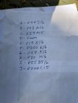
6) I went through and retrieved all the wire numbers from the J37 plug and the corresponding J37 pin Letter (A thru J). Photo attached.

Thoughts on where the instructions went wrong? I want to make darn sure I know which J37 pin letter corresponds to the correct 200B switch Contact before I start cutting.

Thank you
 

Attachments

Guyfang

Moderator
Staff member
Moderator
16,777
24,103
113
Location
Burgkunstadt, Germany
I never hooked a new one up. But I just put a call in to someone who might have done one. Lets see if the old fart will pick up the horn and answer me. So as my Grandpa would have said, "Hold the phone!!" I will get back to you ASAP.
 

Guyfang

Moderator
Staff member
Moderator
16,777
24,103
113
Location
Burgkunstadt, Germany
I still have not heard from him. I was 3 days in Berlin, and now starting to worry about the guy. Will try calling again in the morning.
 

Guyfang

Moderator
Staff member
Moderator
16,777
24,103
113
Location
Burgkunstadt, Germany
I still can not get him to pick up the phone or answer email/Whats app. Starting to get worried now. Its 350 klicks to his house. I might need to take a look see.
 

SLTRAM98

New member
27
23
3
Location
North Carolina
I still can not get him to pick up the phone or answer email/Whats app. Starting to get worried now. Its 350 klicks to his house. I might need to take a look see.
Hopefully your friend is okay. I have spent these past couple weeks reverse engineering this S9 switch. Lots of data coming asap.
 

SLTRAM98

New member
27
23
3
Location
North Carolina
Here is where I stand on organizing all the existing switch information.
1) the S9 switch identifies each termination purpose - it does NOT identify the purpose of the internal secondary relay block that exist outside the top of the control board - I am not sure what it is tripping at the moment.
2) the SW200 will not work (from what I am seeing) as it sits; it is lacking terminals on the crank/start relay. The prior manuals calls for a jumper, but fails to say where or what is being jumped. My plan at the moment (I have not worked it all out yet) is to use a secondary external relay to create the 'missing' relay terminal.
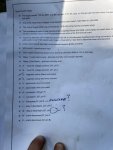
3) Wire mapping is also attached.
 

Attachments

SLTRAM98

New member
27
23
3
Location
North Carolina
Existing OEM wire diagram for S-9 overspeed switch.

Notice the empty terminals: T1, T3, T6

If we look at that, along with the wire diagram on the side of the s9 switch; it tells me:
Relay #1: needs com., NC, and NO - SW200 is missing the NC terminal posts.
Relay #2: needs com., NO - nothing terminates to the NC (T6) posts. e.g. SW200 switch = OK
Relay #3: needs com., NO - nothing terminates to the NC (T3 posts. e.g. SW200 switch = OK and has the extra unused NO terminal as well.

Still working through this, and would always be open to constructive input.
 

Attachments

SLTRAM98

New member
27
23
3
Location
North Carolina
Alright, here is what I think will work. Does anyone mind checking this over? Would prefer to avoid blowing this thing sky high. Please let me know what you all think -
1) Requires a terminal block (TB1) to replace the terminal connections on the empty T15 and T16 from the S9 switch.
2) Requires a simple Relay to create the NC loop on the crank relay.

Let me know what you all think.
 

Attachments

SLTRAM98

New member
27
23
3
Location
North Carolina
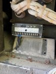
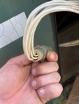
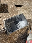
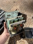
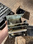
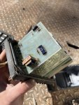
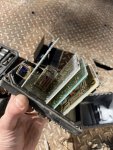
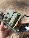
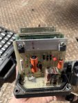
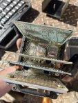
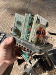
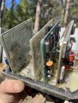
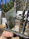
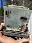
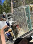
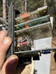
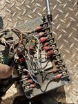
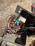
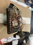
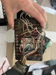
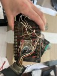
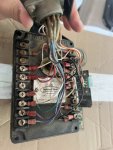
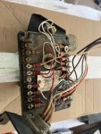
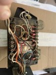
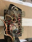
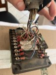
Photos of the S9 switch at various stages for added documentation and review. (I know how hard it is to read and not see this type of stuff).
 

Attachments

Top
AdBlock Detected

We get it, advertisements are annoying!

Sure, ad-blocking software does a great job at blocking ads, but it also blocks useful features of our website like our supporting vendors. Their ads help keep Steel Soldiers going. Please consider disabling your ad blockers for the site. Thanks!

I've Disabled AdBlock
No Thanks