• Steel Soldiers now has a few new forums, read more about it at: New Munitions Forums!

  • Microsoft MSN, Live, Hotmail, Outlook email users may not be receiving emails. We are working to resolve this issue. Please add support@steelsoldiers.com to your trusted contacts.


MEP-016 SX460 AVR shuffle?

Isaac-1

Well-known member
1,970
48
48
Location
SW, Louisiana
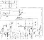
Well tonight it looks like the AVR on my MEP-701a finally died, it has been maxing out with low in hot weather for a while, and during the short power outage at the house tonight it has decided to add a new symptom, very slow voltage swing from about 95-120VAC. Here is my plan, please let me know if you think it is a bad idea:

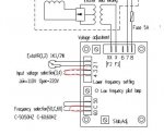
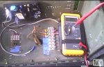
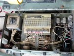
Remove the working military shoe box style AVR from my MEP-016D, replace it with a made in china clone SX460, test the easy to check components for basic operation and tolerance, then put the working military shoe box AVR into my MEP-701a, and pull its flaky shoebox style AVR out to trouble shoot at my leisure.

As I see it this would knock a few pounds off the MEP-016D, being a yanmar retrofit its wiring diagram is already suspect to say the least, so there is less of an issue of it not being by the book, and this would give me a no down time repair option as I will likely have to order components mail order for the bad AVR.

So what are your thoughts, and does anyone have a connection diagram for an SX-460 going into a MEP-016D (Derf?) so I don't have to reinvent the wheel.

Ike
 

derf

Member
926
13
18
Location
LA
I gutted my 701A/016E box and just wired the thing for 120V. But, you should be able to pick up 120V at any stator output. The SX460 just uses the 120 for power (uses very little) and to monitor the output so it can regulate.
If I hadn't deleted my reconnect switch I would look strongly at getting 120V for the SX460 from the convenience outlet feed, before of the fuse.


derf

Member
926
13
18
Location
LA
Looking at the 016B schematic it appears as though the convenience outlet is tied to the same wires (24 and 27) as the VR.

In the pic that part of the diagrams shows 120V to the A2U1 convenience outlet and to the VR. Two wires go from the VR to the field. Two wires go from the VR to the adjustment pot.

Looks like the SX460 would have the same 6 wires and be a piece of cake to swap with the original VR.


Attachments

derf

Member
926
13
18
Location
LA
Here's how I'd do it. (Or, how I did it, kinda.)

Jumpers I added in red. Jump 3 and 4 for low voltage 110/120V operation. Jump C and 60 for 60Hz.

x and xx go to field
7 and 8 go to 24 and 27
1 and 2 go to 28 and 26

See pics.
 

Attachments

Isaac-1

Well-known member
1,970
48
48
Location
SW, Louisiana
That is basically what I had in mind, I already have the SX460, and had added a terminal strip with everything prewired / jumpered so if I had to do this in an emergency I would just move the wires from the terminal strip on the shoe box regulator to the new terminal strip, and not have to back trace all of them in potential bad weather, etc. Did you add in any protective fuses, or diodes for field flashing?

Ike
 

derf

Member
926
13
18
Location
LA
I just ran it bare bones. I can field flash with a couple of wires if necessary so I didn't want any extra stuff.


ETN550

New member
457
9
0
Location
Knoxville, TN
That is basically what I had in mind, I already have the SX460, and had added a terminal strip with everything prewired / jumpered so if I had to do this in an emergency I would just move the wires from the terminal strip on the shoe box regulator to the new terminal strip, and not have to back trace all of them in potential bad weather, etc. Did you add in any protective fuses, or diodes for field flashing?

Ike
Ike,

Will the SX460 take an external voltage adjustment pot?
 

Isaac-1

Well-known member
1,970
48
48
Location
SW, Louisiana
yes it will.

Ike

p.s. I may need a working generator here at the house sooner than I planned, the power went out again for about half an hour just a few minutes ago.
 
Last edited:

derf

Member
926
13
18
Location
LA
The SX460 calls for a 5A fuse in the diagram. You could probably use the spare fuse holder in the 016E. Isn't is just a fuse holder that isn't wired to anything? If not an inline fuse is not expensive.


Isaac-1

Well-known member
1,970
48
48
Location
SW, Louisiana
I plan to install the SX-460 in the MEP-016D over the weekend if nothing comes up, I will try to take photos of each step and post them online when I am done.

Ike
 

derf

Member
926
13
18
Location
LA
Please keep us posted. I have a few projects ahead of the generators but before too long I'll be working on my 003A and my 016E motor with 017 gen head project.
 

Isaac-1

Well-known member
1,970
48
48
Location
SW, Louisiana
Well as it turns out the AVR in the MEP-016D does not match up with the MEP-016B, still I went ahead and installed the SX460 into the MEP-016D, and am ordering another one for the MEP-016B/701A. Anyway Here are the photos and the short version of the write up.

Photo 1, before: with old AVR

Photo 2, close up of the old AVR terminal strip, don't worry about all those wires, only 6 are used, the others just jump from one terminal screw on the AVR to another.

Photo 3, as you can see I added a new terminal strip which I prewired to the SX460 moving the wires across one at a time before mounting it in the MEP-016D, this was handy as the original ring terminal wires are fairly short which would make splicing new push on connectors difficult. For this I recycled a 5 wire wiring harness that had flag connectors on one end and fork connectors on the other, plus added a wire for the 6th wire I needed. I also added a 2 amp fuse between F1 and F2 on the output leg, this was based on max output amps in the TM.

Color coding on the new terminal strip is

Blue and Black to AC input, (wires on old AVR screws 24 & 27)

Orange to F1, (old screw AVR 20)

Purple to F2, (old screw AVR 21 )

Red and White to the front panel voltage knob. (old AVR screws 23 & 26) (note there is a second jumper wire on 23 that goes to 28 )


Now for the little issues, I did have to adjust the SX460 onboard voltage pot next to the purple flag terminal wire (up about 1/4 turn), and the front panel voltage adjustment knob now works backwards (this could be fixed by changing the connections on the back of the knob)

Also note the red LED on the SX460 lights for volt/hz roll offf under about 58 HZ, this is a handy feature to confirm the onboard hz meter reading. Also note the jumpers on the SX460 for 60 Hz mode and 120V reference.

Hope this helps some people


Ike
 

Attachments

Last edited:

Isaac-1

Well-known member
1,970
48
48
Location
SW, Louisiana
Just a little update, today (with no reference to SS archive due to the site outage) I pulled the AVR out of the MEP-701a / 016b and started going through the test procedures in the TM. So far Transistor Q2 tests bad, along with diode CR5 (should read under 50 ohms going one direction, and infinite the other, after scraping off the epoxy coating it tests about 25Kohm one way and infinite the other, then did more scraping still had the same results), next step is unsoldering a leg of CR6, testing it then with CR6 unsoldered and Q2 still removed from its socket, Q1 can be tested without unsoldering. My problem is I can't find CR6, there are a few diodes and resistors with the markings under them so they can't be read, and of course no board layout in the TM, just a logical one. Anyone know where CR6 hides?

Oh on another note, it looks like the newer AVR from the MEP-016b is designed to retrofit in the MEP-016c/-16d as it has alternative screw holes in its mounting plate that matchup with the older style regulator. Too bad I need to go the other way around.

Ike


p.s. anyone else that pulls one of these out note there a 2 screws on the terminal strip between #24 and #26, you can't see the numbers while mounted as they face the bottom of the control box.
 

ETN550

New member
457
9
0
Location
Knoxville, TN
Just a little update, today (with no reference to SS archive due to the site outage) I pulled the AVR out of the MEP-701a / 016b and started going through the test procedures in the TM. So far Transistor Q2 tests bad, along with diode CR5 (should read under 50 ohms going one direction, and infinite the other, after scraping off the epoxy coating it tests about 25Kohm one way and infinite the other, then did more scraping still had the same results), next step is unsoldering a leg of CR6, testing it then with CR6 unsoldered and Q2 still removed from its socket, Q1 can be tested without unsoldering. My problem is I can't find CR6, there are a few diodes and resistors with the markings under them so they can't be read, and of course no board layout in the TM, just a logical one. Anyone know where CR6 hides?

Oh on another note, it looks like the newer AVR from the MEP-016b is designed to retrofit in the MEP-016c/-16d as it has alternative screw holes in its mounting plate that matchup with the older style regulator. Too bad I need to go the other way around.

Ike


p.s. anyone else that pulls one of these out note there a 2 screws on the terminal strip between #24 and #26, you can't see the numbers while mounted as they face the bottom of the control box.
I'm headed out to the garage. I'll see if I can find CR6. I have one apart now that is waiting to be re-capped.
 

ETN550

New member
457
9
0
Location
Knoxville, TN
Okay here are some pics. CR6 is a very small one next to CR7. I started wide then zoomed in.

DSCN3684.jpg

DSCN3683.jpg

DSCN3682.jpg

Let us know how it goes. There is a whole lot of procedure to diagnose that board but, interestingly it is nothing but a bunch of standard resistors, capacitors, diodes, transisters, and a transformer. Therefore, it should be capable of being fixed for little parts money and lots of labor. I like the idea of having a spare then it can be diagnosed and fixed at one's leisure.

I'm also liking the idea of the 460AVR. Do a nice refit like you have and keep a spare one handy.
 

Isaac-1

Well-known member
1,970
48
48
Location
SW, Louisiana
thanks that is a lot easier to read on yours than on mine. Thankfully I have most / maybe all of the stuff to run through the test procedures, although my variable AC power supply is rated half an amp less than the TM calls for, hopefully it will work.

Ike
 

dependable

Well-known member
1,720
187
63
Location
Tisbury, Massachusetts
Let us know how it goes. There is a whole lot of procedure to diagnose that board but, interestingly it is nothing but a bunch of standard resistors, capacitors, diodes, transisters, and a transformer. Therefore, it should be capable of being fixed for little parts money and lots of labor. I like the idea of having a spare then it can be diagnosed and fixed at one's leisure.
In general, do the components wear out at different rates on a board like this? Would it be good or practical to replace all components for a true 'rebuild' or can you replace a couple of components and expect to be all set for a while?
 
Top
AdBlock Detected

We get it, advertisements are annoying!

Sure, ad-blocking software does a great job at blocking ads, but it also blocks useful features of our website like our supporting vendors. Their ads help keep Steel Soldiers going. Please consider disabling your ad blockers for the site. Thanks!

I've Disabled AdBlock
No Thanks