• Steel Soldiers now has a few new forums, read more about it at: New Munitions Forums!

  • Microsoft MSN, Live, Hotmail, Outlook email users may not be receiving emails. We are working to resolve this issue. Please add support@steelsoldiers.com to your trusted contacts.

Mep-1050, mep-1051, 4-1050, 4-1051

jmenende

Well-known member
467
389
63
Location
Puerto Rico
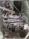
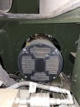
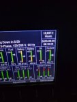
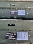
I just got 2 of these units in and its the first time i have seen one. I am impressed with the room available on these to perform repairs or even disassemble. One of the units has 11k hours on it and zero blowby. One thing I noticed was the genhead looks really similar to the 803a but its too bad it wont do 120/240. You can even replace the fuel sender with out having to disassembly half of the unit like on the 1040.
 

Attachments

mciikurzroot

Active member
Supporting Vendor
153
232
43
Location
wimberley texas
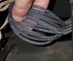
It sure looks like what we are used to seeing, so if indeed you have all 12 of the SAME SIZE wires extending from the housing and likely 2 or 4 smaller ones you would be good to go for 120/240 but you need to verify the TOTAL number of wires from the or coming out of the stator body, but you must have on the 12 side of this that they are all the same size, just having 12 total is not the panacea answer, we cant mix and match large and small wires just so we get 12 wires.. IF you have 4 smaller ones is good 2 will power the AVR and 2 will supply DC voltage back from the AVR to excite the generator proper, let us know, if you just have 2 thats ok as well, it will work just fine as long as you got the 12 same size.. if i sound like I'm repeating or driving home the 12 wires , well i am, its because most persons have a 10 lead generator and 2 more for Field excitation, but its not the same .. mac/mc
 

jmenende

Well-known member
467
389
63
Location
Puerto Rico
It sure looks like what we are used to seeing, so if indeed you have all 12 of the SAME SIZE wires extending from the housing and likely 2 or 4 smaller ones you would be good to go for 120/240 but you need to verify the TOTAL number of wires from the or coming out of the stator body, but you must have on the 12 side of this that they are all the same size, just having 12 total is not the panacea answer, we cant mix and match large and small wires just so we get 12 wires.. IF you have 4 smaller ones is good 2 will power the AVR and 2 will supply DC voltage back from the AVR to excite the generator proper, let us know, if you just have 2 thats ok as well, it will work just fine as long as you got the 12 same size.. if i sound like I'm repeating or driving home the 12 wires , well i am, its because most persons have a 10 lead generator and 2 more for Field excitation, but its not the same .. mac/mc
Yes I completely understand and will double check. 10 wires has been the norm for all 804ab and larger units from that series. I assumed it was the same for the ammps series but you know what they say about assumptions. Will report back.
 

kloppk

Well-known member
Steel Soldiers Supporter
2,149
3,532
113
Location
Pepperell, Massachusetts
Wow, :eek: The available TM's for this set is very inconsistent! So it may not be a 12 wire head even though the -24P shows 12 wires.

The -24P TM dated 1 July 2011 indicates switch S501 is used to change the output phase/voltage and that it has 3 settings for 120/240, 120/208 & 120 and a 12 wire head.
The -10 TM dated 1 February 2011 indicates the set can only do 208 or 416 3 phase and reconnection is done with a reconnection plate like the 804,5,6's

Sure wish there were accurate TM's for the set....
 

uniquify

Active member
228
223
43
Location
Sioux Falls, SD
I just got 2 of these units in and its the first time i have seen one. I am impressed with the room available on these to perform repairs or even disassemble. One of the units has 11k hours on it and zero blowby. One thing I noticed was the genhead looks really similar to the 803a but its too bad it wont do 120/240. You can even replace the fuel sender with out having to disassembly half of the unit like on the 1040.
Any chance you can get a picture of the tag on the gen head? It should be just left of the lifting loop in your middle picture. That should clear things up.
 

jmenende

Well-known member
467
389
63
Location
Puerto Rico
Yes I completely understand and will double check. 10 wires has been the norm for all 804ab and larger units from that series. I assumed it was the same for the ammps series but you know what they say about assumptions. Will report back.
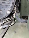
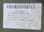
Ok. Confirmed it has 12 same sized wires. Also has the f1,f2 and another pair. The genhead plate specifies 120/240 @doble delta. There is hope.
 

Attachments

kloppk

Well-known member
Steel Soldiers Supporter
2,149
3,532
113
Location
Pepperell, Massachusetts
Ok. Confirmed it has 12 same sized wires. Also has the f1,f2 and another pair.
Other pair would be the Quad Winding Output.

Can you find where each of the 12 leads go? Do they go to individual posts on the reconnection block? If so that would good.
The TM's for the 1050 are useless for determining that.
The DCS might get confused if reconfigured for 120/240. Don't know...
 

Guyfang

Moderator
Staff member
Moderator
16,784
24,129
113
Location
Burgkunstadt, Germany
Wow, :eek: The available TM's for this set is very inconsistent! So it may not be a 12 wire head even though the -24P shows 12 wires.

The -24P TM dated 1 July 2011 indicates switch S501 is used to change the output phase/voltage and that it has 3 settings for 120/240, 120/208 & 120 and a 12 wire head.
The -10 TM dated 1 February 2011 indicates the set can only do 208 or 416 3 phase and reconnection is done with a reconnection plate like the 804,5,6's

Sure wish there were accurate TM's for the set....
There are accurate TM's. We just cant get them.
 

jmenende

Well-known member
467
389
63
Location
Puerto Rico
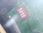
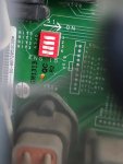
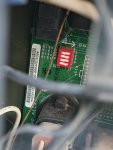
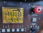
So this is what I learned today while tinkering with the 15kw. I swapped (2) 60kw control cubicles and they registered as 15kw units immediately on display with no changes made by me in the configuration. Only got a message that the configuration changed and the message went away after I hit fault reset. I figured the dip switch in back of connection board tells the control box what model unit its on and changes automatically and thus is labelled as "engine id". I have included the dip configurations from my 10kw,15kw and 60kw in case someone needs them. Also the pics of the control board models i used. Looks like these control boards are interchangable as far as i know. I have about 5 other control boards in stock and will run the same test with those of they are of a different model. I will also send pics of the connection board to try and figure out if this unit can be rewired and how the generator will react to that. Will need help from the electrical gurus on this forum.
 

Attachments

kloppk

Well-known member
Steel Soldiers Supporter
2,149
3,532
113
Location
Pepperell, Massachusetts
From my understanding of the set that dip switch setting is read by the DCS at power up to let the DCS know if it's in a 1030, 1040, 1050, 1060 or 1070. The DCS then responds accordingly based on that dip switch setting.
That's why they immediately knew they were in a 1050.
The engine dip switch settings are documented in respective TMs.
 
Top
AdBlock Detected

We get it, advertisements are annoying!

Sure, ad-blocking software does a great job at blocking ads, but it also blocks useful features of our website like our supporting vendors. Their ads help keep Steel Soldiers going. Please consider disabling your ad blockers for the site. Thanks!

I've Disabled AdBlock
No Thanks