• Steel Soldiers now has a few new forums, read more about it at: New Munitions Forums!

  • Microsoft MSN, Live, Hotmail, Outlook email users may not be receiving emails. We are working to resolve this issue. Please add support@steelsoldiers.com to your trusted contacts.

MEP-112a to MEP-003a conversion 400Hz to 60Hz

CUCV_ut

Member
89
11
8
Location
Ogden, UT
I found a great deal on a MEP-112a generator last summer. The seller included a 60Hz generator head from a MEP-003a generator for converting it over.
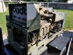
20190629_171826.jpg
I researched it and discovered that I would also need a different control panel and output box as well. I have a non-running mep-002a and found that the output box could be converted for a MEP-003a by removing half the loops of wire in the current transformer to make the output breaker trip at the higher 10KW output. The control box from the MEP-002a should work ok on the 003a according to what I researched. I found one thread on here with a little information but it mostly confirmed they had switched it after the fact. I hope to add a few more pictures of the work in progress and go over the process. If anyone has some experience to add to this please chime in.
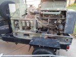
20190629_200929.jpg

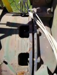
First I took off the control panel. It mounts with 4 vibration dampers that have a single bolt from inside the control panel. Most of them ended up just spinning the mount and would not come loose. If you look at the mount where the control penal bolt screws in there is a round hole in the side. I used a punch that fit the hole to hold it from spinning while I removed the bolts. Disconnect the large connectors from the back. There is a small ground strap on the bottom of the control box that goes to the frame, be sure to disconnect it.

Next I removed the output box. That was pretty simple. Just remove the connectors then there are 4 bolts in the back of it. Then remove the front cover and there are two more at the bottom edge.

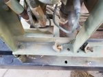
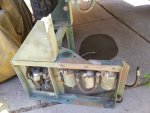
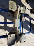
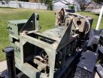
Next I removed the metal frame that hold the control panel and fuel pumps. Disconnect the fuel lines coming from the tank and the one to the injector pump. Disconnect the 3 Packard connectors going to the fuel pumps and label them so you know where they go. Disconnect the connector from the fuel solenoid. There are 6 bolts around the edge of the frame.
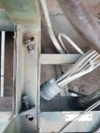
20200711_080102.jpg 20200711_080130.jpg
20200711_114027.jpg

Next remove the 2 fuel tank straps, the connector for the fuel sender, and the fuel return hose. Lift the fuel tank up and remove it. This allows access to the bell housing bolts and generator mounts.
 

CUCV_ut

Member
89
11
8
Location
Ogden, UT
I actually read in the other thread that they tried to adjust the RPM while the 400Hz generator was intact. The MEP-112a runs at 2200 RPM but the MEP-003a runs at 2000 RPM max. I was not sure how would be a good way to measure that, so I tried a photo tachometer on the generator fins (removed the screen cover around it). You adjust the maximum speed screw on the front of the engine by the fan grille. I wasn't getting a good reading of RPM, so I decided to get the process started and adjust it once I had it reassembled. This was also because I suspect the control panel had an issue with the relay for the starter making it difficult to get the starter to engage. Hopefully when I swap control panel this will be resolved.

An important note here- Please keep a copy of the MEP-003A-Intermediate-and-Depot-Level-Maintenance-Manual-TM-5-6115-585-34 manual handy. It covers the generator end removal and installation.

20200711_110904.jpg
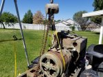
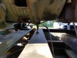
I setup the portable gantry and hoist. Next we removed the nuts that hold the generator to the bell housing. I also removed the four bolts that secure each generator mount to the skid. Once the generator housing and engine separate there will be nothing holding up that end of the engine. I noticed a bolt underneath the bell housing that looked like it was put there to support and adjust the engine height. I cranked it up till it touched.
20200711_085143.jpg

I applied a little bit of lift the tapped around the generator engine line with a chisel to break it free.
20200711_110909.jpg

At this point I had forgotten the 8 flywheel generator bolts. They are in sets of two and have a metal retainer plate that you have to carefully bend back the corners on so you can undo the bolts. I used a flat tip screwdriver to bend them. Just be sure you are careful to get them flat again so the wrench can get on the bolt securely. I removed the 4 bolts securing each of the generator mounts to the skid. The generator assembly should now separate from the engine.
20200712_074427.jpg

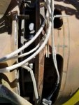
I was having trouble getting it to come off (before I read the TM again and realized I forgot the 8 flywheel bolts) so I undid the the cover of the generator end to take a look. You don't really have to take the cover off the end, but I'll leave them for reference.

20200711_110918.jpg
I figured I might have to remove the 4 bolts in the center in case they were holding the bearing end of the generator in. After working on it for a while the whole end cover came off.
20200711_113926.jpg
We worked it a little more and got it to move another inch but that was about it. The tools literally got to hot to touch from the sun so we went inside until it cools down later.
20200711_113954.jpg
 
Last edited:

Guyfang

Moderator
Staff member
Moderator
16,985
24,767
113
Location
Burgkunstadt, Germany
I would try reading the TM. The removal procedure is very well written. I am going to guess, that you have not removed all the Main Gen Fan screws, that mount the fan to the flywheel.

A MEP-002A control box is the same as what fits a MEP-003A gen set.

There may be some parts in the AC output box that are NOT the same, between the 002A and 003A. You should check that out closely.

There is more to do then just changing the loops through the CT on the AC output boxes. If there wasn't, the NSN's would be the same between the 002A and 003A. And they are not the same.

There is also an adjustment that needs to be made to allow the 002A box to function right on a 003A set.
 

CUCV_ut

Member
89
11
8
Location
Ogden, UT
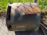
Thanks Guyfang. I had read the TM but forgot the flywheel bolts. I would suggest printing the appropriate pages and checking them off as you go. I edited the above procedure to specify which manual has the instructions and added the part about removing the flywheel bolts so I don't confuse anyone. I lifted the old generator off and set it aside. Here is a picture of the 400 Hz generator end.
20200712_091048.jpg
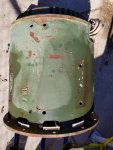
Here's a picture of the 60 HZ unit.
20200712_091036.jpg
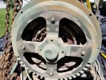
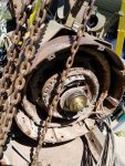
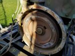
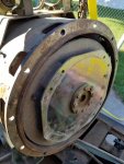
As you can see, the 60 Hz generator is smaller diameter than the 400 Hz generator, that would be a very quick way to which head you are working with. Here's a picture of the flywheel and of the generator end plate where it connects.
20200712_081655.jpg
20200712_081701.jpg
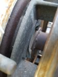
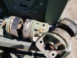
Here's a picture of the generator mount assembly. The 60 Hz head uses two spacers between the mount and the generator, the 400 Hz unit does not need the spacers. I had to use the mounts off the 400 Hz head as the ones on my 60 Hz head were rotten. The spacers can be seen to the right of the mount in the photo.
20200712_091042.jpg
Bad generator mounts I removed.
20200719_112929.jpg
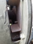
To mount the new head you will want to make a couple studs to screw into the flywheel to keep it lined up with the flex plate and generator fan while sliding it into position. The TM has info on making them, I just used a couple of longer bolts and cut the heads off. Make sure they're not too long or you will not be able to unscrew them once the generator is in position. the picture below shows one of the alignment studs. I just used pliers to unscrew them after I put a couple of the actual bolts in. Install the 8 bolts with locking plate. Tighten the 8 bolts and then bend the tabs f the locking plates down to secure them. Tighten all the bell housing bolts down. Lower the bolt that was supporting the engine. Install the bolts for the generator mounts to the skid.
20200714_085417.jpg
Next I want to touch up the paint and clean up the 60 HZ head before I proceed.
 

CUCV_ut

Member
89
11
8
Location
Ogden, UT
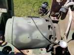
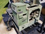
I painted the generator end and had to drill out two bolts and re-thread the holes for the end cover. Next I put back the supporting frame then the output box. Leave all the bolts for the framework loose until you get the output box connected to the frame, it was a tight fit to get all the holes to line up.
20200719_112923.jpg

20200719_112912.jpg

20200719_112936.jpg

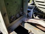
I guess I should have tagged the two big cables going from the generator to the output box. They both look the same but one has a wire that connects to the skid ground. Now I've got to research weather it's J9 or J10 that has the plug with the ground wire.
20200719_112918.jpg
 

Guyfang

Moderator
Staff member
Moderator
16,985
24,767
113
Location
Burgkunstadt, Germany
There is supposed to be a tag on the cables, listing P9 and P10.

P-9 Wires T-1, T-7, T-3, T-9, T-2, T-8 all hook to J9
P-10 wires T-5, T-11, T-4, T-10, T-6, T-12 all hook to J10
 

CUCV_ut

Member
89
11
8
Location
Ogden, UT
Thanks for the wiring info Guyfang. I finally got the generator back together. But, it doesn't put out any power. The good news is it started up and ran fine. I tried holding the start switch to flash the field, but still registered no voltage out. I started going through the troubleshooting steps for the generator, I probably should have done that before I bothered mounting it. I did notice that this wiring chart does answer the question about which plug is P9 and P10 for those of us who no marking left on them.
mep003a generator.jpg

mep003a generator 1.jpg
I followed the h2 winding resistance test. I found most pairs had similar resistance at around .35 ohms. Then I tested between A (ground lead attached to the frame) and C (T12) on P10 and got .5 ohms. I tried the other lead from that winding (T9, pin E on P9 plug) and it shows a short to ground too. I gather this means that that winding is shorted out? Is there anything that can be done to fix it or do I need another stator? I guess lesson learned, run all these tests when you first pick up a "working" generator end.
 
Last edited:

Guyfang

Moderator
Staff member
Moderator
16,985
24,767
113
Location
Burgkunstadt, Germany
It sounds like the main gen is shorted, yes. You could take it to a shop, and have them rewind it. But Its probaly cheaper to find another main gen.
 
Top
AdBlock Detected

We get it, advertisements are annoying!

Sure, ad-blocking software does a great job at blocking ads, but it also blocks useful features of our website like our supporting vendors. Their ads help keep Steel Soldiers going. Please consider disabling your ad blockers for the site. Thanks!

I've Disabled AdBlock
No Thanks