• Steel Soldiers now has a few new forums, read more about it at: New Munitions Forums!

  • Microsoft MSN, Live, Hotmail, Outlook email users may not be receiving emails. We are working to resolve this issue. Please add support@steelsoldiers.com to your trusted contacts.

MEP-114A GPU

Guyfang

Moderator
Staff member
Moderator
17,940
26,849
113
Location
Burgkunstadt, Germany
Yeah i think youre right for it being an air leak source, and also correct on the location, that is from the fuel selector to the first pump.
So cleaned out everything, new filters and it will run. Remember that IDLE/RUN toggle on the front i told yall about? Well it will change the rpm from low speed to operating speed so not sure what thats about, its also finnicky and i will have to toggle it up and down sometimes to keep at operating rpm. When running and start switch held and Voltage/Amp knob on L1-L0 i get 120vac on the genset gauge, toggle CKT BRKR switch to CLOSE and i get 120v on each leg measured at the main connection point, HTZ gauge reads 0 though, (OK. The hertz meter is driven by the A2, (Frequency Converter). Open the control panel and test the input side of the A2. You should get 120 VAC, 400 hertz there. If so, the A2 or the M6, (Freq Meter) is bad. If you have a half way decent DMM, it will measure hertz. Just stick it in the 120 volt outlet, (make sure its hooked up and the CB-3 is pushed in. If you get no reading at CB-3, go to the output load terminals and test there. Use the AC volt adjuster to get 120 volts and the hertz adjuster to 400 hertz. You want to make sure the A-23, (electric governor) and A-24, (Electric Actuator) are working.) will that only show a reading when its outputting a load? (No. It works all the time)
When it cools down im going to pull the head off the injection pump and see how it looks since it seems to be hunting up and down (Do you mean the A24 is moving up and down? Or you can hear the hertz/RPM moving up or down. ) a little…might also be because theres no load? (No. This is a Precise Power gen set. If the A-23 and the A-24 are working right, the Hertz should be ROCK steady) Give me some input on that one.

Going to throw some diesel cleaner in the tank, just for piece of mind for the long run. (Look in the tank with a light. You should be able to see to the bottom and it should be clear, not cloudy. Look for water, it will look like quicksilver in the fuel tank. )
Regulator in alternator (you mean the G2, battery charging alternator?) is shot i think, at operating rpm the output is 32vdc and i have the manual voltage adjuster (you mean the pot on the alternator) on it turned all the way down. (Keep in mind, you operate this set at less than rated speed, you risk damaging the A-11, (Static Exciter)
The front side fuel pump was bad, tore it down, cleaned it and tried to test it straight from the battery and nothing, (I would soak it 1-2 days in a fluid that eats diesel lacquer) even tried beating the shit out of it and no joy, rear pump works great though and is currently installed all by itself. (normal fix. good job) Yall know the approximate working fuel pressure this should be at? Probably going to a COTS option entirely.

Now on to the 28vdc box. The tag says Input is 3-phase, 200v, 400htz so i switched the genset to L3-L1 which gives me 200vac on the gauge but no reading on the hobart box for DC input.
 
Last edited:

azreark1

New member
19
8
3
Location
Dallas, TX
So when you say A2, A24, etc., are you referring to their label on a wiring schematic? Im still working on deciphering it.
Worries me though with other people having their greedy little hands in this and just rigging it…
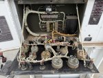
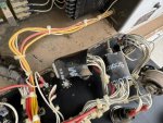
So remember that pesky Idle/Run switch? So it is the one on the right in the picture with two red wires going to it, one goes to the start/stop toggle and the other follows the yellow wires to the splice at the Governor Control Unit. If i had to guess, one of the toggles you see wrapped in 3M tape goes in the empty space between the Panel Light and Run/Idle switch, and the other is the REAL switch that is supposed to be where the current Run/Idle switch currently sits.
And then on top of that, they removed the Freq and Volt adjustments from the panel and just have them ziptied to the harness, my initial thought would be so that nobody could mess with it.
Should the Synchronization lights be clear? I think someone painted over them with black paint…


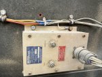
Genset Panel1.JPEGGenset Panel2.JPEGGCU1.JPEG


Sent from my iPhone using Tapatalk
 

Guyfang

Moderator
Staff member
Moderator
17,940
26,849
113
Location
Burgkunstadt, Germany
So when you say A2, A24, etc., are you referring to their label on a wiring schematic? Im still working on deciphering it. (Yes, that is the ID in the siring scematic, and printed next to each item.)
Worries me though with other people having their greedy little hands in this and just rigging it…
So remember that pesky Idle/Run switch? So it is the one on the right in the picture with two red wires going to it, one goes to the start/stop toggle and the other follows the yellow wires to the splice at the Governor Control Unit. If i had to guess, one of the toggles you see wrapped in 3M tape goes in the empty space between the Panel Light and Run/Idle switch, and the other is the REAL switch that is supposed to be where the current Run/Idle switch currently sits.
(Look at the wire numbers and then at the schematic.Make sure the unit is NOT in the parallel switch position. That will stop it from starting)
And then on top of that, they removed the Freq and Volt adjustments from the panel and just have them ziptied to the harness, my initial thought would be so that nobody could mess with it.
Should the Synchronization lights be clear? I think someone painted over them with black paint…
(Like Scobby said, don not worry about them unless you want to parallel)

Open a parts wanted thread for the load bank. There has been from time to time, someone selling one in the forum.
 

azreark1

New member
19
8
3
Location
Dallas, TX
Okay so i started one of those, and then looking at the TMs...theres some different numbers. I see the different publication dates for the TMs, so would the 9-6115-465-24P be the correct one to work off of? Has most recent publication date but has different Load Bank model numbers between it and the -12.

EDIT: Kind of disregard, different model numbers but basically the same NSN number? the -24 just has a couple extra 0's.
 

LuckeyD

Active member
78
241
33
Location
Vilseck, Germany
Time to show my age. I hated these things. I thought they all went away. Guyfang and I worked missile systems and other things that used 400HZ power all over the planet. with me for 50 years. Using a few HP bridge rectifiers and a 400HZ transformers and CAPS you have enough to start a 747 or two here. This is a 3 phase 400HZ 30KW generator with about 100 AMPs per phase and a 7.5A exciter fused 24-28VDC battery charging system with a 35A Alternator in your picture. Had bigger ones too.

As Guy stated the fuel system is a great starting point. The fuel pickup in the tank will have crud in it so blow that out backwards. Look in the onboard tank for how much rust is in there as they did rust blocking the fuel pickup. The last ones came from RESET with a plastic tank 25 years ago. Those electric fuel pumps had a filter in the bottom (fig 50 item 8 in the parts manual) so this needs cleaned/replaced. Now all cleaned out with fuel pickup in a 5 gallon gas can, (useDF2) it should pump with the pump output in a bucket at 5-7PSI. Check hoses as they did have an issue where the inside would separate from the outer wall and block fuel. They used air hoses till this was found, by an old fat guy in a Patriot unit in Hanau at Underwood Kaserne and this set had 50 gallons of water in it as well 23 years ago. Put the day tank on a bench and clean everything ensuring all works, and seals back up, and now go on to filters (change the elements and screens) and eventually you get to the fuel injection pump.

I carried a fuel pump I connected to the batteries and bypassed all the before to see if they messed up the injection pump and usually found it working. Guy hit it as these are supposed to start holding it in start till you see AC show up on the gage as it comes up to speed(400HZ), and wear ear protection as these are noisy things. . Older ones had a field flash circuit (showing age here). Starting was on a plate on the left door of the control panel no one read. Now on the right side under the control box is a speeder which must be pulled out a bit so the electric actuated precise speed control in your picture on the right side of the main gen can control the RPM so it can generate 400HZ as in idle it won't do that and no ACV either, run rough, and do all sorts of funny things.

An electronic actuator controls engine RPM set by this control if the speeder is pulled out a bit as I flew in a Helo 2 hours to find this at a unit in a war zone with a heat seeking missile almost taking me out. The engine will eventually smooth out and these engine are really golden if you keep coolant systems on order and change oil and use clean fuel. It ain't pretty when a unit puts airplane fuel or jet fuel in the tank and starts it up. Boom. Try the fuel system clean out and let us Know how it goes. That big box on top was an incorporated load bank the business that made it went outa business a long time ago. This one is 400Hz so it won't work well on a normal 60HZ system. Internal relay coils won't energize and go futz. Had a Lieutenant plug in a hair blow dryer that did not last long. Teeth sparkled for a moment. I could only laugh after I saw she was OK. Let us know how it goes. 400HZ, oh boy I hope it makes power.
 
Last edited by a moderator:

Guyfang

Moderator
Staff member
Moderator
17,940
26,849
113
Location
Burgkunstadt, Germany
Okay so i started one of those, and then looking at the TMs...theres some different numbers. I see the different publication dates for the TMs, so would the 9-6115-465-24P (Date 1992, with change #2) be the correct one to work off of? Has most recent publication date but has different Load Bank model numbers between it and the -12. ( What date and how many changes to the two TM's you looked at. ? When looking for parts, always use the -24P. Thats what its for. Did you download your TM's from the forum here? They are as far as I know, the newest and most updated ones I have ever seen.

EDIT: Kind of disregard, different model numbers but basically the same NSN number? the -24 just has a couple extra 0's.
(When you see a case of two or more model numbers, but the same NSN, its because at some point the origanal part supplier, for what ever reason no longer supplies that part to the military. Another part supplier steps in, to fill the gap. If the part is a drop in replacement, the NSN will not change.)

If you find this Load Bank Kit, I will not only eat my hat, but yours. They were not produced or issued in great numbers. Simply find another one, that will fill the bill.
 
Top
AdBlock Detected

We get it, advertisements are annoying!

Sure, ad-blocking software does a great job at blocking ads, but it also blocks useful features of our website like our supporting vendors. Their ads help keep Steel Soldiers going. Please consider disabling your ad blockers for the site. Thanks!

I've Disabled AdBlock
No Thanks