• Steel Soldiers now has a few new forums, read more about it at: New Munitions Forums!

  • Microsoft MSN, Live, Hotmail, Outlook email users may not be receiving emails. We are working to resolve this issue. Please add support@steelsoldiers.com to your trusted contacts.

Mep-802a ac short fault.

GlennBigg

New member
3
0
1
Location
North Florida
Hi everyone ,I have read this forum for several years and learned a lot, thanks for all the info. I have a Mep 802 that trips shortly after a modest load (3 kw) is turned on. No load it’s fine. Turning on battle short has no effect on the problem . Usually it shows a short fault light but some times a overload light shows instead. Never both lights.It will continue to output if you hold the ac enable switch up. This problem started around the same time the Voltage regulator on the 28 volt alternator failed. That has been replaced and charging system is working normally. I have owned and used the machine for several years with no issues. Does the fact that battle short switch doesn’t affect the problem mean that the burden resisters ,current transformer and S6 are not part of the problem? Any ideas where to look next. I have a good background in electricity and mechanics ( retired aircraft mechanic ) ,but I am still learning about this machines protective circuits.
Thanks for all the time everyone takes helping us newbies out.
Glenn
 

kloppk

Well-known member
Steel Soldiers Supporter
2,091
3,415
113
Location
Pepperell, Massachusetts
The Battle Short switch cannot inhibit Short Circuit faults. See the -10 TM

Poor contact in the S6 and S8 can cause this type of issue.
With the set OFF exercise S6 and S8 by moving them repeatedly thru all positions and then set them back to their needed positions before starting. If you have contact cleaner such as Deoxit spray that into the guts of the switches before exercising them.
See if that helps with the problem.

If not then there are some voltage measurements you can make at the K8 relay to determine if the issue is internal or external to K8.
 

GlennBigg

New member
3
0
1
Location
North Florida
The Battle Short switch cannot inhibit Short Circuit faults. See the -10 TM

Poor contact in the S6 and S8 can cause this type of issue.
With the set OFF exercise S6 and S8 by moving them repeatedly thru all positions and then set them back to their needed positions before starting. If you have contact cleaner such as Deoxit spray that into the guts of the switches before exercising them.
See if that helps with the problem.

If not then there are some voltage measurements you can make at the K8 relay to determine if the issue is internal or external to K8.
What TM and section describes the operation and testing of K8?
 

kloppk

Well-known member
Steel Soldiers Supporter
2,091
3,415
113
Location
Pepperell, Massachusetts
If there is a section on testing K8 it would be in the -24 TM.
The tests I mentioned are my own used to narrow down problems with Overload and Short Circuit Faults.
 

Guyfang

Moderator
Staff member
Moderator
16,438
23,395
113
Location
Burgkunstadt, Germany
Hi everyone ,I have read this forum for several years and learned a lot, thanks for all the info. I have a Mep 802 that trips shortly after a modest load (3 kw) is turned on. No load it’s fine. Turning on battle short has no effect on the problem . Usually it shows a short fault light but some times a overload light shows instead. (The Short Circuit fault and Overload fault are almost the same thing, as a short is detected by the gen set putting out what looks like an overload. And as Kurt wrote, the S7 will not over ride those problems) Never both lights. (The A2 Fault Indicator can only react to one fault at a time) It will continue to output if you hold the ac enable switch up. (This is NOT a good idea. What if you gen set has a short in it? You are forcing the K1 relay to stay closed, when something is telling it to open.) This problem started around the same time the Voltage regulator on the 28 volt alternator failed. That has been replaced and charging system is working normally. I have owned and used the machine for several years with no issues. Does the fact that battle short switch doesn’t affect the problem mean that the burden resisters ,current transformer and S6 are not part of the problem? (Not at all. I once had to find a fault for short Circuit problem, and it was in the burden resisters. Test everything. assume nothing. Thats why Kurt is telling you to test the K8 first. It could be bad, or, you could have a another problem in the set. ) Any ideas where to look next. I have a good background in electricity and mechanics ( retired aircraft mechanic ) ,but I am still learning about this machines protective circuits.
Thanks for all the time everyone takes helping us newbies out.
Glenn
 

kloppk

Well-known member
Steel Soldiers Supporter
2,091
3,415
113
Location
Pepperell, Massachusetts
Now that I'm back to a real computer and reference materials I can give you more info on the K8 "Relay" operation and expand on the voltage tests you can do at the K8 Overload/Short Circuit "Relay".
The K8 relay monitors the current load on each of the 3 legs of the generator to determine if the 3 legs are loaded within normal levels, overloaded or in a short circuit condition. If it "thinks" it detects either an Overload or Short Circuit it will cause the Contactor to open (Battle short OFF for Overload) and cause the respective Fault Lamp to illuminate.

Here is how the system operates... (basics)
Thru a combination of S6, S8, the %Load Meter, R13 and the Burden Resistors R10, R11 & R12 and the Current Transformer they generate 3 AC voltages that are then fed to the K8 relay. Each of the 3 AC voltages that are sent to K8 represent the level of load on each of the 3 legs of the generators output.
The 3 AC voltages that represent the detected Load of each of the 3 legs can be measured at the following K8 Terminal pairs:
K8-1 and K8-4
K8-2 and K8-4
K8-3 and K8-4

What does S6, S8, the %Load Meter, R13 and the Burden Resistors R10, R11 & R12 and the Current Transformer do you may ask?
The current Transformer generates 3 AC currents (not voltages) that are proportional to the load on each of the 3 generator legs.
The other parts take the AC current (not voltage) developed by the current transformer and converts it to 3 AC voltages which then are fed to K8. If they are all operating correctly and no wiring issues they will provide K8 with the correct AC voltages that are proportional to the AC load on each generator leg. If there issues with this circuit due to component degradation, poor contacts, etc it will cause incorrect (usually higher than normal) AC voltages to be sent to K8.
Incorrect high AC voltages to K8 can cause it to "think" there is an Overload or Short Circuit condition when there actually isn't one.

Normally the AC voltages at these terminals ranges from ~0 VAC at 0% Load up to ~5.6 VAC at 100% Load. (~7.5 VAC at 133% Load)
So approximately 5.6 mV AC / 1% Load.

The K8 monitors these 3 AC voltages. If any of these 3 AC voltages exceeds 110% Load (6.16 VAC) for some defined period of time the K8 will trigger an Overload Fault. The greater the Overload the quicker it will trigger an overload fault.
If any of these 3 AC voltages exceeds 425% Load +/- 25% (23.8 VAC +/- 25%) the K8 will immediately trigger an Short Circuit Fault.

So... what you can do is start the set and apply your "small" load that doesn't trip the Overload Fault.
Set the AM/VM switch so you can read the %Load on the set. The %Load should correspond to the actual load you applied.
Use the formula (%Load * 0.056 V) to determine what AC voltage you should be reading at the K8 terminals.
Then CAREFULLY measure the AC voltage at the K8 terminal pairs and see if one or all three measure the calculated voltage. If one or more are way high then this will generally point to a problem with S6, S8, the %Load Meter, R13, the Burden Resistors R10, R11 & R12 or the Current Transformer.
Measure across...
K8-1 and K8-4
K8-2 and K8-4
K8-3 and K8-4

If the AC voltage present match's what you calculated then you should gradually increase your load, recalculate the expected AC voltage at K8 and reverify at K8. If you get an Overload Fault and all 3 of the AC voltages at K8 and below 5.6 VAC then you likely have a bad K8.

If you find that K8 is defective it may have been damaged when the regulator in your alternator went bad and possibly damaged K8.

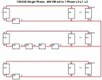
Here is a diagram of the connections when running 120/240 Single Phase for the CT, S6, S8, M8, R10, R11, R12 & K8.
The CT's generate AC currents based upon the load on each leg it detected. When operating correctly S6, S8 & M8 exhibit virtually zero resistance.
The current generated by each CT is then passed to the respective Burden Resistor R10, R11 or R12. The current flowing thu the Burden Resistors causes a AC voltage drop to develop across each burden resistor. The connections between K8 to each of the burden resistors provide the AC voltage developed across the resistors to K8. K8 monitors these 3 AC voltages to determine if there is any OL or SC condition.
Burden Resistor Schematic.JPG


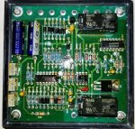
For inquiring minds... here are the innards of a Technology Research Corporation 19230 88-21141 K8
K8 Inside.jpg

Hopefully this will help you diagnose your sets issue and others who may peruse this thread in the future.
 
Last edited:

GlennBigg

New member
3
0
1
Location
North Florida
Now that I'm back to a real computer and reference materials I can give you more info on the K8 "Relay" operation and expand on the voltage tests you can do at the K8 Overload/Short Circuit "Relay".
The K8 relay monitors the current load on each of the 3 legs of the generator to determine if the 3 legs are loaded within normal levels, overloaded or in a short circuit condition. If it "thinks" it detects either an Overload or Short Circuit it will cause the Contactor to open (Battle short OFF for Overload) and cause the respective Fault Lamp to illuminate.

Here is how the system operates... (basics)
Thru a combination of S6, S8, the %Load Meter, R13 and the Burden Resistors R10, R11 & R12 and the Current Transformer they generate 3 AC voltages that are then fed to the K8 relay. Each of the 3 AC voltages that are sent to K8 represent the level of load on each of the 3 legs of the generators output.
The 3 AC voltages that represent the detected Load of each of the 3 legs can be measured at the following K8 Terminal pairs:
K8-1 and K8-4
K8-2 and K8-4
K8-3 and K8-4

What does S6, S8, the %Load Meter, R13 and the Burden Resistors R10, R11 & R12 and the Current Transformer do you may ask?
The current Transformer generates 3 AC currents (not voltages) that are proportional to the load on each of the 3 generator legs.
The other parts take the AC current (not voltage) developed by the current transformer and converts it to 3 AC voltages which then are fed to K8. If they are all operating correctly and no wiring issues they will provide K8 with the correct AC voltages that are proportional to the AC load on each generator leg. If there issues with this circuit due to component degradation, poor contacts, etc it will cause incorrect (usually higher than normal) AC voltages to be sent to K8.
Incorrect high AC voltages to K8 can cause it to "think" there is an Overload or Short Circuit condition when there actually isn't one.

Normally the AC voltages at these terminals ranges from ~0 VAC at 0% Load up to ~5.6 VAC at 100% Load. (~7.5 VAC at 133% Load)
So approximately 5.6 mV AC / 1% Load.

The K8 monitors these 3 AC voltages. If any of these 3 AC voltages exceeds 110% Load (6.16 VAC) for some defined period of time the K8 will trigger an Overload Fault. If any of these 3 AC voltages exceeds 425% Load +/- 25% (23.8 VAC +/- 25%) the K8 will immediately trigger an Short Circuit Fault.

So... what you can do is start the set and apply your "small" load that doesn't trip the Overload Fault.
Set the AM/VM switch so you can read the %Load on the set. The %Load should correspond to the actual load you applied.
Use the formula (%Load * 0.056 V) to determine what AC voltage you should be reading at the K8 terminals.
Then CAREFULLY measure the AC voltage at the K8 terminal pairs and see if one or all three measure the calculated voltage. If one or more are way high then this will generally point to a problem with S6, S8, the %Load Meter, R13, the Burden Resistors R10, R11 & R12 or the Current Transformer.
Measure across...
K8-1 and K8-4
K8-2 and K8-4
K8-3 and K8-4

If the AC voltage present match's what you calculated then you should gradually increase your load, recalculate the expected AC voltage at K8 and reverify at K8. If you get an Overload Fault and all 3 of the AC voltages at K8 and below 5.6 VAC then you likely have a bad K8.

If you find that K8 is defective it may have been damaged when the regulator in your alternator went bad and possibly damaged K8.

Here is a diagram of the connections when running 120/240 Single Phase for the CT, S6, S8, M8, R10, R11, R12 & K8.
The CT's generate AC currents based upon the load on each leg it detected. When operating correctly S6, S8 & M8 exhibit virtually zero resistance.
The current generated by each CT is then passed to the respective Burden Resistor R10, R11 or R12. The current flowing thu the Burden Resistors causes a AC voltage drop to develop across each burden resistor. The connections between K8 to each of the burden resistors provide the AC voltage developed across the resistors to K8. K8 monitors these 3 AC voltages to determine if there is any OL or SC condition.
View attachment 823337


For inquiring minds... here are the innards of a Technology Research Corporation 19230 88-21141 K8
View attachment 823338

Hopefully this will help you diagnose your sets issue and others who may peruse this thread in the future.
Thank you so much, as soon as I finish my barn chores I am off to the shop. The schematic for the burden resistors is a huge timesaver and should be in the schematic in the TM .Very nicely done.
 
Top