• Steel Soldiers now has a few new forums, read more about it at: New Munitions Forums!

  • Microsoft MSN, Live, Hotmail, Outlook email users may not be receiving emails. We are working to resolve this issue. Please add support@steelsoldiers.com to your trusted contacts.

MEP-802A and MEP-803A Wire diagrams

Guyfang

Moderator
Staff member
Moderator
16,777
24,103
113
Location
Burgkunstadt, Germany
Morning sleepy heads!

I am working on, (if I don't go insane first) improving the wire diagrams for the MEP-802A and Mep-803A generators. Sadly, I don't have one, to run out to and look at, when I have a stupid question. I have already found one mistake. The manuals have crappy wire diagrams. The form is good, but the quality is crappy. Soooooooooo, I figured I might be able to improve things.

I need someone to look, the next time they stick their nose into the control panel, at the ground points. The is a ground point on the control panel door, with a couple wires on it. I need to know the wire numbers.

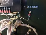
I also need the wire numbers on the Control Panel Ground Point. It's in the back of the control panel box. There may also be another ground point there. I KNOW there is one for the A1, volt regulator, where the coax shields for two wires 156A and 157B are grounded. I THINK there are several other wires grounded there, but am not sure.

So would one of you big strong men take a gander for me? I may have other requests, but am on the verge of losing my mind doing this. So we will take it a step at a time.

Take care and have a wonderful day!! In any case better then the rain and snow we have had of late. I hate winter!

Guy
 

csheath

Active member
714
213
43
Location
FL
If my unit ever had numbers they are all gone except a #3 band on the signal terminal of the temperature gauge (M6).

IMG_1863.jpg
 

Guyfang

Moderator
Staff member
Moderator
16,777
24,103
113
Location
Burgkunstadt, Germany
I have seen that before! For some reason, the wire number faded away. I was looking for a short, and about went crazy. This was in 2004? I was using an old, old, old schematic. There were a number of mistakes. I went in search of another set, and then copied wire positions and wire numbers. It worked, but I was grumpy forever.
 

kloppk

Well-known member
Steel Soldiers Supporter
2,145
3,526
113
Location
Pepperell, Massachusetts
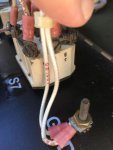
On my 802 there two wires on the ground post on the control panel door.
They appear to be labelled: 100AW20 & 100L20

The ground port to the right of the A1 Regulator has two wires on it.
The one that is the ground for the shield does not appear to be marked. It's a small white wire with a black stripe on it.
The second wire on the post appears to be marked: 100AF20
 
Last edited:

Zed254

Well-known member
866
466
63
Location
S. Hampton Roads, VA
MEP-803A reset 2012: Cover 100L20, 100AW20. Back panel:100AF20 and another unnumbered wire that appears to be tied into VR terminals 1 and 2. Cover 100L20.jpgPanel 100AF20.jpgPanel Crimped to VR1,2.jpg100AW20 Cover.jpg

MEP-802A reset 2008: Cover 100L20, could not read # on companion wire. Panel 100AF20 and unnumbered as above.
 
Last edited:

DieselAddict

Well-known member
Steel Soldiers Supporter
2,532
2,059
113
Location
Efland, NC
If you have any remaining gaps I'll be happy to look over the units I have when I get home in December.
 

mciikurzroot

Active member
Supporting Vendor
153
232
43
Location
wimberley texas
Guy perhaps I can help. I have the wiring diagrams on 11x17 and 17x24 printed size paper, very easy to read. In my case i grew tired of playing with the screened ones riveted onto the sets respective doors [802a/803a/and 804b i speak of.. I drilled out the rivets then went to a photo shop and had the door mounted ones reversed negatives made and onto paper so i didn't have to keep lugging around the sharp edged door mounted schematics. this effort was not terribly expensive but did and does save me a lot of time bending over or sitting on the ground trying to read what i want, then getting up and tracing or finding the wire path, where with the schematic in hand i just use the point to point location to verify wiring and continuity for whatever i am searching for.. my point ? i will be pleased to go back down to the local Kinkos and have a copy made and send to you of whatever ones you want if at all.. as best i recall it averaged out near $5.00 a sheet and i forget the price i paid for the photo shop to reverse the drawings.. Also if you want i will go and review the GROUND points on my units and confirm or as you might want .. thanx mac/mc Oh and certainly this applies to any of who might need or want the schematic in paper form.. mm
 

DieselAddict

Well-known member
Steel Soldiers Supporter
2,532
2,059
113
Location
Efland, NC
What Guy and myself are doing is to make readable electronic copies of the wiring diagrams and wire lists for maintenance and repair purposes. Having a printed copy is absolutely handy. What we want to end up with is a nice clean set of electronic files to go with the TMs.
 

Guyfang

Moderator
Staff member
Moderator
16,777
24,103
113
Location
Burgkunstadt, Germany
Guy perhaps I can help. I have the wiring diagrams on 11x17 and 17x24 printed size paper, very easy to read. In my case i grew tired of playing with the screened ones riveted onto the sets respective doors [802a/803a/and 804b i speak of.. I drilled out the rivets then went to a photo shop and had the door mounted ones reversed negatives made and onto paper so i didn't have to keep lugging around the sharp edged door mounted schematics. this effort was not terribly expensive but did and does save me a lot of time bending over or sitting on the ground trying to read what i want, then getting up and tracing or finding the wire path, where with the schematic in hand i just use the point to point location to verify wiring and continuity for whatever i am searching for.. my point ? i will be pleased to go back down to the local Kinkos and have a copy made and send to you of whatever ones you want if at all.. as best i recall it averaged out near $5.00 a sheet and i forget the price i paid for the photo shop to reverse the drawings.. Also if you want i will go and review the GROUND points on my units and confirm or as you might want .. thanx mac/mc Oh and certainly this applies to any of who might need or want the schematic in paper form.. mm

I thank you very much sir! But like Mike wrote, we want to produce readable schematics that we can upload to be used in conjunction with the TM's. And there is several mistakes with the schematics in the TM's and the plates on the gen set. The ones in the TM's are simply crap.

I am also working on a list, so you can look up any wire number, and see from what point to what point the wire goes. I also thought we might toss in some helpful hints. Like any wire number that has the 100 in it, is a ground wire. Or that the last two numbers of a wire number are the wire size, (gage). Or that the last two numbers can ( and often are) left off, On the diagrams.

I have to admit, that was a great idea to use reverse negative printing! I bet it's nice to have a bigger view of the circuits. In the 80's I had a plate for every gen set in the army, in my shop. Also, in the old days, the schematics came in the books, extra, extra, extra large. I always covered them in plastic, so we could use China markers on them. Handy learning tool.
 

csheath

Active member
714
213
43
Location
FL
I must have been cornfused on this. So the wire numbers are printed directly on the wire insulation? I guess I didn't look close enough. I have the one wire with a number band on it so I assumed the numbering should all be on bands.
 

mciikurzroot

Active member
Supporting Vendor
153
232
43
Location
wimberley texas
Guy/Mike thank you both for this effort, as well my long delayed answer.. The weather has been so good i have just lost myself in my shop and barn getting things sorted put up and tossed as well.. The fire pit has consumed a lot of junk and many many boxes
these past two weeks and i have floor space again.. For the effort i have at hand [readily available] bot an 803 and 802 and easy access to it so if i can help verify or trace feel free to ask ..and for future i picked up an 804a last week .. it had been returned with 'burnt' wiring, the person or group who bought it hooked up something wrong and burned back quite a bit of ground wiring it looks like as best i could tel, it is on a trailer and i had to take the trailer as well and for me climbing around or working with emm on the trailer is a RPIA the 804 maxs out my tractor to lift off and get onto ground level then i have if you need access to several 804B at the station .. So ifi can help just let me know .. You are so so right the old foldout schematics were near useless, lord the army was slow to change, i can take a small credit, it was actually Col Cross from the late -mid 90's who led MEP at that time who listened and began to make improvements in the manuals and the whole series, the leading 'cause' was the fact of having to get GREEN emission or prove exemption compliant for the 2000 years that really opened their eyes and made MEP command sorta get modernized as much as they would allow themselves anyhow, but it was a big leap still today.. in closing the point to point wiring list was a must for the loom builders and trouble shooting and many many thanks for you all doing this effort. best: mac/mc
 

Guyfang

Moderator
Staff member
Moderator
16,777
24,103
113
Location
Burgkunstadt, Germany
OK,

Back i n the saddle, at least a bit. The computer works, but still no spell check. Oh well, will get that under control sooner or later.

NOW, thank you all that sent in info!! I am not done yet, but now can open up my files and work again. So I may be tapping you all again. Now I need to see if all my files are still here and if I need to get more then the spell check fixed.

Later all!

Guy
 

Triton

Active member
240
81
28
Location
Houston, Texas
Guy and Mike, can't wait to see what y'all come up with, if I can help with pics of my 803 please let me know. Glad to help!
Keith
 

majoday

Active member
84
155
33
Location
Bloomburg,TX
Guy perhaps I can help. I have the wiring diagrams on 11x17 and 17x24 printed size paper, very easy to read. In my case i grew tired of playing with the screened ones riveted onto the sets respective doors [802a/803a/and 804b i speak of.. I drilled out the rivets then went to a photo shop and had the door mounted ones reversed negatives made and onto paper so i didn't have to keep lugging around the sharp edged door mounted schematics. this effort was not terribly expensive but did and does save me a lot of time bending over or sitting on the ground trying to read what i want, then getting up and tracing or finding the wire path, where with the schematic in hand i just use the point to point location to verify wiring and continuity for whatever i am searching for.. my point ? i will be pleased to go back down to the local Kinkos and have a copy made and send to you of whatever ones you want if at all.. as best i recall it averaged out near $5.00 a sheet and i forget the price i paid for the photo shop to reverse the drawings.. Also if you want i will go and review the GROUND points on my units and confirm or as you might want .. thanx mac/mc Oh and certainly this applies to any of who might need or want the schematic in paper form.. mm
This is very interesting. I have been looking at the schematic and the wiring diagram on my MEP-803A (built in 2000, 78 hrs on the Hobbs, bought for $750.00 from a local guy) to understand the set. My first AF job was in radio repair, 66-70. So, I've dusted off the memories and looked at the genset schematic and wiring diagram as well as the color coded one in the forum. Did you publish your 11X17? I noticed you are in Wimberly, I live on a farm 20 miles South of Texarkana, TX.
 

mciikurzroot

Active member
Supporting Vendor
153
232
43
Location
wimberley texas
With no disrespect to the others who have proffered the paper solution, i went a different route...
the schematic did me no good on the door both schematics i speak of.. so i took emm off found some old political yard sign material [coraplast] cut it about 1/2" extra width and heigth glued the aluminum pabel [schematic] to the coraplast and identified it with my lable maker and for me its so freeking easy to read and handel, i omitted i also ran whilt 3/4" electrical tape around the edges and then folded it over the edges and let it stick onto the back side so i wasnt having to deal with the rough/sharp coraplast edges.. i dont loose it its pretty weatherproof and i just store em all in a drawer. for me it was the best way to go ... easy to sit down and read, never gets folded or torn any of that nonssense, i can orient the schematic any direction and while seated or standing, none of the standing on our head trying to follow the wire or item locations ... good luck mac/mc
 
Top