• Steel Soldiers now has a few new forums, read more about it at: New Munitions Forums!

  • Microsoft MSN, Live, Hotmail, Outlook email users may not be receiving emails. We are working to resolve this issue. Please add support@steelsoldiers.com to your trusted contacts.

MEP 802A Load Meter only showing about 1/4 what it should

pclausen

Well-known member
Steel Soldiers Supporter
452
281
63
Location
Afton, VA
This is a continuation of the Picked up 6 MEP-802A gensets and will be documenting making them all runners here thread.

This thread is specifically about the unit where the ammeter is showing a very low reading.

I know the ammeter itself is ok since I swapped it with the one in my 803 set, where it was working fine.

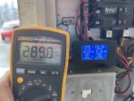
I have my meter connected in series with the ammeter as follows:
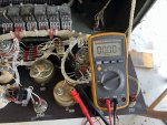
IMG_0790.JPG

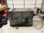
I did some additional load testing today, after straightening out all the panels and doors and putting them on the set.

I started out like this:
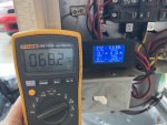
IMG_0781.JPG

And progressed to this:

IMG_0787.JPG

Here's a table of the loads I used:

Load 1.0 PF (Watts)Load 0.8 PF (Watts)Ammeter reading (mA)Frequency (Hz)
1,6102,01368.261
2,3202,90099.161
4,3005,375187.560
5,6707,088254.859
6,4008,000289.059

My understanding is that the current flowing through the ammeter should be 1000 mA @ 133% load, which would be around 6,650 Watts. The closest load I was to to do, was 7,088 Watts, which only produced 255 mA as measured by my meter.

Other than the ammeter reading low, the set seems to be performing better and better as the rings are seating. Only a 2 Hz drop from a 2 kW load to a 8kW load is pretty good I think.

The overload protection would have probably kicked in after a couple of minutes of running at 8,000 Watts, but I only ran at that load for about a minute.

I didn't recheck the voltages across R10-R12 on the runs today, but I took the following readings a few days ago:

Resistor2.26 kW4.10 kW
R100.66 V1.36 V
R110.49 V1.34 V
R122.80 V4.96 V

Any idea what could be causing the ammeter to read about 25% of what it should be?

On a side note, one of the reasons I didn't slap the panels on right away, is that they were all in pretty bad shape:
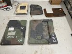
IMG_0775.JPG

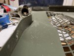
Especially the roof over the engine:

IMG_0776.JPG

But it looks a lot better now:

IMG_0791.JPG

After getting the document door straight, I even painted it to get it kinda close to match the rest of the panels on that side:
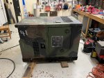
IMG_0792.JPG

Its not perfect, but at a causal glance, I think it looks ok. Still need to work on the fuel tank cover. As you can see if the photo above of all the panels, the one on this set was made out of steel! I'll have to sand it down and prime it before putting it back on. Other than being made out of steel, it matches my other fuel tank covers perfectly, louvers and all.
 

Guyfang

Moderator
Staff member
Moderator
16,920
24,542
113
Location
Burgkunstadt, Germany
A number of things come to mind
1) Gen head leads hooked to wrong TB3 terminals
2) Wrong leads from TB3 running thru the CT2
3) Wrong number of turns of wire thru CT2

4) Bad CT
5) other...

This is what came to mind the other night when you first started writing about this problem.

#3 happens WAY too often.
#'s 1&2 are even more often. Its what happens when too many hands have been in a set, and when people mark wires, instead of comparing the schematics and the hardware.

Word of warning. The small wires on the CT's. It real easy to break off the studs, on the CT's. I learned to give them a shot of break free or something like that the night before I wanted to take the wires off.

Also, the M1 & M8. From the factory, they come with plastic covers on the input studs. Working in the control panel, while the set runs, can, from time to time, lead to you sometimes letting your arms lower a bit. Get your arm across one of those meters, and it will perk up your sex life. Lots of folks think the caps are not needed. I dont. Been there 2-3 times, and its not nice.
Open to read comments.
 

pclausen

Well-known member
Steel Soldiers Supporter
452
281
63
Location
Afton, VA
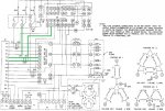
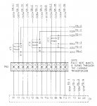
Ok, I went through and verified the paths marked in green on the below schematic:

S8 wiring diagram - Copy.jpg

I also counted the number of turns of the wires through CT2 and the total is 16. I'm 99% certain the count is 8 each of 002A and 008A as per the diagram below:

CT wiring.jpg

I removed the wires from A1, B1 and C1 and got 0.4, 0.6 and 0.7 Ohm respectively, across each CT. Guy you're right about those nuts being tight, especially on C1 in my case.

I don't know what else it could be at this point...

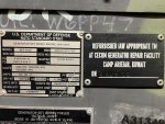
This set was build in 2007 and reset in 2010. Hour meter shows 7,500 hours, which presumably is after the reset.

IMG_0797.JPG

Is the guy that reset each set also the guy that stamps the date on it? (look at the "1" on the tag above)
 

pclausen

Well-known member
Steel Soldiers Supporter
452
281
63
Location
Afton, VA
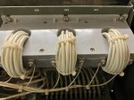
Yours looks to be 2x4 count for each CT vs. the 2x8 count on mine. That would make sense since a 803 makes twice the power of a 802, so half the windings to get to 100% on a 1A ammeter.

Here's mine: (before I cut the zip ties to count the turns)

IMG_0795.JPG
 

kloppk

Well-known member
Steel Soldiers Supporter
2,168
3,610
113
Location
Pepperell, Massachusetts
Have you used your load bank on other sets and do their %Load meters work OK?

Have you cleaned contacts 1-6 in P6 and J6?
The CT signals go thru those contacts.

If K8 was bad it may influence the %Load reading. You might try disconnecting the two wires on K8-2 and connect the two wire lugs together. This will disconnect the load signal to K8 thus isolating it. See if the %Load meter reads right.
 

pclausen

Well-known member
Steel Soldiers Supporter
452
281
63
Location
Afton, VA
Yes, I have used that load bank on both another 802 and a 803, and in both cases, the readings on the load bank digital display corresponded to the %Load meter readings.

I pulled P6 from J6 and sprayed both insides with contact cleaner really well and plugged and unplugged several times. No difference.

I pulled both K8-2 wires and connected the lugs together. No difference.

I think what I'm going to try next, is to swap out the entire control box from my spare set, so see what I get. I'll of course have to move over the voltage regulator and the gauges from the spare, since those are known to be busted.
 

pclausen

Well-known member
Steel Soldiers Supporter
452
281
63
Location
Afton, VA
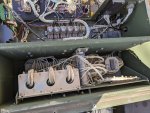
Got the control box removed and replaced with my spare. While I had it out, I verified that all 12 wires from the genhead are wired correctly to TB3:

IMG_0798.JPG

After transferring the voltage regulator to the other control box along with the fuse mod, I discovered that wire 106B (# 8 ) was too short to reach the fuse block:

IMG_0799.JPG

I'll solder on an extension piece tomorrow so that it will reach. Curious why the end of that wire was cut off and a new lug crimped on. I also need to replace all those rusted screws on the terminal barrier.

I noticed that somewhere along the way, someone must have had fun with S6 since all the wires were not neatly bundled up:

IMG_0800.JPG

I'll get all that cleaned up as well once I know that this control box fixes the issue with the %Load meter. It will be interesting to see what other gremlins are hiding in this newly swapped in control box from my spare. This for sure has been the most stubborn set I have worked on yet...
 
Last edited:

pclausen

Well-known member
Steel Soldiers Supporter
452
281
63
Location
Afton, VA
Got the 106B wire extended so that it would reach the fuse block. Unit was completely dead what I tried to start. Tracked that down to a bad CB1 breaker. I bypassed is and was able to fire up the unit. I had my meter connected in series with the ammeter but, alas, I get 0 mA when putting a load on the set, no matter how large.

I checked the resistance through the ammeter, and it was around 1 Ohm, so not open, which could have accounted for the 0 mA reading. My guess is that someone ran run into something similar with the set that control box was originally in (my spare 802), and had started to mess with S6, but decided to bail.

So I'll switch back to the original control box since it at least shows about 25% of what it should. It wasn't a complete waste however, as I discovered the fuel gauge worked in this panel, along with all 3 green panel lamps. So I'll swap those over into the original panel, along with swapping the voltage regulator back over. I'll also take the time to thoroughly clean contacts 1-6 in P6 and J6 since I'll have easy access, on the off chance that is the culprit.
 
Top
AdBlock Detected

We get it, advertisements are annoying!

Sure, ad-blocking software does a great job at blocking ads, but it also blocks useful features of our website like our supporting vendors. Their ads help keep Steel Soldiers going. Please consider disabling your ad blockers for the site. Thanks!

I've Disabled AdBlock
No Thanks