I have broken two voltage regulators so far.
Talking with Kurt (a great guy, he has been a great help with the 2wire start and the voltage regulator), he had me meter the wire from 5&6 on the voltage regulator.
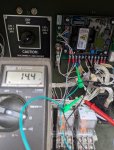
I get 14.4 ohms between 5&6.

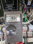
Between 5 & ground, I end up with 4.38m ohms

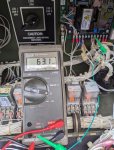
Between 6 & ground, I end up with 63.1k ohms

Last month I picked a new to me MEP-802A to possibly do a stator swap with my low hour mep-802A.
Between 5&6 on the new one I have 12.4 ohms.
Between 5 & ground, I have 8.43M ohms.
Between 6 & ground, I have 8.61M ohms.
I was expecting this to be an open circuit. We thought that the ground issue is why my voltage regulator is having issues.
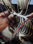
I have also removed the control section to test the wire pairs per RM 9-6115-631-24 (I think this is the older TM).
Between T1 & T4 I had 10.6 ohms.
Between T2 & T5 or T3 & T6 I can't get a good reading it keeps on moving. Could this be because I haven't removed the stator from the genset and the rotor is affecting the reading?

What else should I do before I just pull the stator from the old one and put it in the newer one? I don't know that I am going down the correct path.
Thanks in advance.
Talking with Kurt (a great guy, he has been a great help with the 2wire start and the voltage regulator), he had me meter the wire from 5&6 on the voltage regulator.
I get 14.4 ohms between 5&6.

Between 5 & ground, I end up with 4.38m ohms

Between 6 & ground, I end up with 63.1k ohms

Last month I picked a new to me MEP-802A to possibly do a stator swap with my low hour mep-802A.
Between 5&6 on the new one I have 12.4 ohms.
Between 5 & ground, I have 8.43M ohms.
Between 6 & ground, I have 8.61M ohms.
I was expecting this to be an open circuit. We thought that the ground issue is why my voltage regulator is having issues.
I have also removed the control section to test the wire pairs per RM 9-6115-631-24 (I think this is the older TM).
Between T1 & T4 I had 10.6 ohms.
Between T2 & T5 or T3 & T6 I can't get a good reading it keeps on moving. Could this be because I haven't removed the stator from the genset and the rotor is affecting the reading?

What else should I do before I just pull the stator from the old one and put it in the newer one? I don't know that I am going down the correct path.
Thanks in advance.


