• Steel Soldiers now has a few new forums, read more about it at: New Munitions Forums!

  • Microsoft MSN, Live, Hotmail, Outlook email users may not be receiving emails. We are working to resolve this issue. Please add support@steelsoldiers.com to your trusted contacts.

MEP 803 A M8 % load gauge not working

jaybird67k

Member
74
23
8
Location
Texas
So first off thanks for all the help on my genset. My last post started as something else then wandered off when I found my M8 % load gauge isn't working.
Several on here had some great suggestions for troubleshooting and provided some good diagrams.
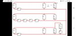
I'm currently looking for a good diagram of the S6 swith because it's difficult to read with the wires in the way.
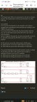
I have tested continuity on almost all of the connections in the diagram with good results. The resistor R11 I'm assuming needs to be disconnected to actually test resistance?
I have continuity across it.

Thanks, Jason
 

Attachments

kloppk

Well-known member
Steel Soldiers Supporter
2,090
3,411
113
Location
Pepperell, Massachusetts
To check the resistance of any of those resistors you need to disconnect the wire(s) from one end of the resistor first.

S6 "odd" Terminals
1726759561150.png

S6 "even" terminals
1726759667356.png
 
Last edited:

jaybird67k

Member
74
23
8
Location
Texas
To check the resistance of any of those resistors you need to disconnect the wire(s) from one end of the resistor first.
Thanks kloppk. I thought so because I work with resistors on various things.
On the diagram you sent me it shows it coming from M8 to S8 to 44 then to 43.
I believe 43 is on top of S8 above 44 but 43 has nothing connected to it.
 

kloppk

Well-known member
Steel Soldiers Supporter
2,090
3,411
113
Location
Pepperell, Massachusetts
S8 is similar to S6 on how the terminals are arranged.
All odd numberer terminals on one side and evens on the other.
Here is a shot of some of S8's odd terminals.
1726760113567.png

1726760265826.png

1726760333957.png
 

jaybird67k

Member
74
23
8
Location
Texas
Thanks, do you have a shot of S6 without wires on it?
I have checked continuity with everything except for one leg of switch to S6 #28. Can't see #28 for the wires.

Also haven't checked resistance on R11.
The screws that hold R11 in are insulated it seems so I need to check at wire connections?

Thanks
 

jaybird67k

Member
74
23
8
Location
Texas
So I clipped one leg of my meter on to the CT2 on B2 and checked all the way around from B2 back through #7 at S6 down the line and have continuity all the way around.
Mind you when I checked through M8 I checked the left post with the door open.
The right post of M8 is wire 162A that turns into 162B before terminating at #44 on S8.
I have no continuity there but it does read 120 ohms. This is the wire I made the splice on near S8 because it was chewed in half.
Should I have good continuity there?
Maybe I made a bad butt connection?

Also on R11 Im getting 10.5 ohms at the wires with one side unscrewed and 3.5 ohms on the metal tabs where the screws go.

Thanks, Jason
 

Guyfang

Moderator
Staff member
Moderator
16,437
23,392
113
Location
Burgkunstadt, Germany
As much as you will not care to hear this, the best way to check a switch is to take all the wires off the darn thing. Remove it and i would put it in a vice so it wont move. Then check it.

Tip. If you do this, take a wire off and then tighten the screw up. Not hard, just a little bit firm. Why? Because there are "Jumpers" in the switch. They are removable. If you lossen up all the wires and then pull the switch out, you might just see all the Jumpers fall out. Then you have get them all back in the right place. Then hook up the wires IAW the wire diagrams. I NEVER mark wires with terminal numbers. Why? Because if someone else hooked it up wrong you will just repeat his mistake.
 

kloppk

Well-known member
Steel Soldiers Supporter
2,090
3,411
113
Location
Pepperell, Massachusetts
M8 terminal 1 to J6-7 is wire 162A. P6-7 to S8-44 is wire 162B.
If you are measuring 120 ohms, then you may have a bad splice or poor connection between the contacts J6-7 and P6-7
..............Wire 162A.........................................Wire 162B
M8-1------------------------J6-7/P6-7------------------------S8-48

The mounting bar that runs thru R11 and sticks out both ends of R11 is isolated from the resistor itself.
 

kloppk

Well-known member
Steel Soldiers Supporter
2,090
3,411
113
Location
Pepperell, Massachusetts
You should have good continuity, zero-ish ohms, between all the points in my diagram. If you don't then you need to dig into the wiring path between the two points.
 

jaybird67k

Member
74
23
8
Location
Texas
You should have good continuity, zero-ish ohms, between all the points in my diagram. If you don't then you need to dig into the wiring path between the two points.
Should the continuity be the same through the diagram going both ways?
What I mean is from both post of M8 through the system?
 

jaybird67k

Member
74
23
8
Location
Texas
So I clipped 162B where I made the splice and checked it with it cut with bare wire. Weird thing is.
162B that goes back to 162A to the right post of M8 is open.
Here is the weird part. When I check the cut side going to #44 of S8 to right terminal of M8 I get 120 ohms 🤔 and its not connected. Same number I was getting when it was connected.

Any thoughts.

Remember this genset only has 45 hours on it and it had not been touch as far as I can tell until I found those rat chewed wires.

Thanks, Jason
 

Ray70

Well-known member
2,500
5,562
113
Location
West greenwich/RI
Sorry to back track, but has the load meter ever worked for you?
If not, you should also check all of the internal jumper connections on your switch.
At one point I worked on a 802 that appeared to have the correct switch installed but it turned out that NONE of the internal jumpers were present.
Looking at the wiring diagram you can see all of the jumped connections, just use your meter to verify continuity between them.
Kloppk's picture shows the jumpers on the outside of the switch, but if you have the other style switch the jumpers are internal and not as readily visible.
 

Ray70

Well-known member
2,500
5,562
113
Location
West greenwich/RI
Or perhaps it really does only have 45 hours on it.... because no one ever used it, because it's been problematic since day 1, so it sat around doing nothing for years!
Everyone wants the super low hour machines, but I'll take something that has been used a bit and proven over time over the one that sat collecting dust all its life any day!
 

jaybird67k

Member
74
23
8
Location
Texas
Sorry to back track, but has the load meter ever worked for you?
If not, you should also check all of the internal jumper connections on your switch.
At one point I worked on a 802 that appeared to have the correct switch installed but it turned out that NONE of the internal jumpers were present.
Looking at the wiring diagram you can see all of the jumped connections, just use your meter to verify continuity between them.
Kloppk's picture shows the jumpers on the outside of the switch, but if you have the other style switch the jumpers are internal and not as readily visible.
Which switch and picture are you referring to with the jumpers?
S6 ?
 

jaybird67k

Member
74
23
8
Location
Texas
No M8 hasn't worked since I have owned it but I just got it up and running after fixing the chewed wires removing the tank to clean it and doing the fuse and MOV mod.
I just recently got this machine.
 

Ray70

Well-known member
2,500
5,562
113
Location
West greenwich/RI
Sorry, I'm talking about S6, the AM/VM selector switch. any missing or incorrect connections, as well as bad connections inside the switch ( dirt corrosion etc ) can cause inoperable and / or incorrect readings on the load meter, as well as false overload warning lights.
The yellow lines show the 13 internal connections that need to be in place. Not sure, but have you tried cleaning the switch yet?
If the jumpers are all correct, I would then clean it with a good contact cleaner / protectant.

S6 jumpers.JPG
 

jaybird67k

Member
74
23
8
Location
Texas
Sorry, I'm talking about S6, the AM/VM selector switch. any missing or incorrect connections, as well as bad connections inside the switch ( dirt corrosion etc ) can cause inoperable and / or incorrect readings on the load meter, as well as false overload warning lights.
The yellow lines show the 13 internal connections that need to be in place. Not sure, but have you tried cleaning the switch yet?
If the jumpers are all correct, I would then clean it with a good contact cleaner / protectant.

View attachment 931896
Ok thanks a bunch.
Does internal jumpers mean I need to take it apart?
 

Ray70

Well-known member
2,500
5,562
113
Location
West greenwich/RI
Don' take it apart yet, just probe the screws where you see the yellow bars to verify if they are connected internally. ( you can barely see an internal copper bar in the terminal if you know what you're looking for, but it's foolproof if you use your DMM.
IF by chance you find 1 or more missing connections you can create those connections by installing a short jumper wire between the screws of the missing connections and then retest.
 
Top