• Steel Soldiers now has a few new forums, read more about it at: New Munitions Forums!

  • Microsoft MSN, Live, Hotmail, Outlook email users may not be receiving emails. We are working to resolve this issue. Please add support@steelsoldiers.com to your trusted contacts.

MEP-803 fuel pump Length discrepancy

Sidis8

Member
Steel Soldiers Supporter
47
47
18
Location
Nj
Hey guys

pump number 2 won’t produce any fuel while cranking with the line off. Looking through the engine tm, on 3-23, it says to shim the pump. Never done this before, anybody have any experience with this procedure ?
Thanks for any help in advance
 

Light in the Dark

Well-known member
Steel Soldiers Supporter
3,860
6,074
113
Location
MA
Have you taken the pump out to see if you can compress the spring by hand, to get any fuel out of it? It could be that the pump is stuck compressed, so no matter where the cam lobe falls, its not mechanically pumping.
 

Sidis8

Member
Steel Soldiers Supporter
47
47
18
Location
Nj
Have you taken the pump out to see if you can compress the spring by hand, to get any fuel out of it? It could be that the pump is stuck compressed, so no matter where the cam lobe falls, its not mechanically pumping.
yes I did, it compresses by hand and fuel comes out. Looking at it more, it seems like there’s too many shims for this pump. I’m gonna take #1 pump off tomorrow and measure those shims.

what’s The best way to get the pin aligned on the pump with the fuel rack when putting it back in ? I’m having a heck of a time making it fit properly with the rack
 
Last edited by a moderator:

Light in the Dark

Well-known member
Steel Soldiers Supporter
3,860
6,074
113
Location
MA
How did you remove the pump in the first place? Ideally you loosen the backing nut on the top FSS stop bolt, and adjust the bolt a little closer to the radiator (so the FSS can articulate more closed). With that done, the notches in the fuel rack armature line up better with the opening in the engine block that the rack pin is supposed to line up with. Its done this way so that they cant unseat themselves under normal use.

With the pump out of the machine, you should be able to manually move the FSS armature 'open', and with a finger into the opening for the metering pump on the block, feel where the pin notch is in relation to the FSS movement. So when you determine where the rack should be, you take the metering pump and put it back into position... that rotating pin should drop right into the notch if you have it lined up properly. It should sink right in like magic. Then make sure the barb on the pump is pushed 'back' towards the push rod tube as much as it will allow (this will allow for maximum fuel delivery, but make sure both pumps are clocked to a similar position) and then put the cast iron keep back on the pump and tighten it down. Readjust the FSS stop and see if she runs.
 

Sidis8

Member
Steel Soldiers Supporter
47
47
18
Location
Nj
Hello again everyone

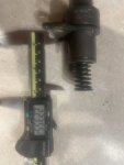
another night messing with this 803. Ran across something strange, the tm, figure 3.11 on page 3-24 states this lenght is supposed to be 2.02 inches. I’m measuring one of the pumps and getting 2.23 inches. That’s almost a quarter longer than the tm says. Am I doing something wrong here ? Or is the pump missing that many shims ? I’ll attach a picture of the measurement, I realize it’s laying down next to it but can’t take a good picture holding both up. Still trying to figure out how to measure the depth from the crankcase to the fuel pump tappet cap.

Thanks for any help in advance
 

Attachments

loosegravel

Just a retired mechanic who's having fun!
504
892
93
Location
Enumclaw, Washington
I was just looking at the Lister Petter master parts manual. It seems that they've used (4) different fuel pump manufacturers. They show Lucas Dizel as the "current" one. Part #751-41322. Past manufacturers are Omap, Bryce and Stanadyne. It's possible that the drawing and the specs shown above are of one manufacturer but may not apply to another?
 

loosegravel

Just a retired mechanic who's having fun!
504
892
93
Location
Enumclaw, Washington
It appears that there are (3) different threads from sidis8 now on the same topic. Would it be possible to combine them all in one thread? It may get better results.

When reading the other threads, it appears that cylinder #2 was not producing any fuel out of that pump. Much like swapping spark plugs or spark plug wires in a gas engine from one hole to another to see if the engine miss changes too, it may help to diagnose something like a flat cam lobe by swapping IP's? Just a suggestion.
 

loosegravel

Just a retired mechanic who's having fun!
504
892
93
Location
Enumclaw, Washington
Hello again everyone

another night messing with this 803. Ran across something strange, the tm, figure 3.11 on page 3-24 states this lenght is supposed to be 2.02 inches. I’m measuring one of the pumps and getting 2.23 inches. That’s almost a quarter longer than the tm says. Am I doing something wrong here ? Or is the pump missing that many shims ? I’ll attach a picture of the measurement, I realize it’s laying down next to it but can’t take a good picture holding both up. Still trying to figure out how to measure the depth from the crankcase to the fuel pump tappet cap.

Thanks for any help in advance
The thickness of the shims under the IP's is for timing purposes only. The amount of shims under the IP's should not make any difference for whether or not the IP will make pressure. The rule of thumb is to reinstall the same shims that came out. The procedure for determining what the shim thickness should be for each of the IP's is rather lengthy and requires some special tools along with some knowledge. That's why it's a good idea to keep track of what shims go where when the IP's are rremoved.
 

Sidis8

Member
Steel Soldiers Supporter
47
47
18
Location
Nj
The thickness of the shims under the IP's is for timing purposes only. The amount of shims under the IP's should not make any difference for whether or not the IP will make pressure. The rule of thumb is to reinstall the same shims that came out. The procedure for determining what the shim thickness should be for each of the IP's is rather lengthy and requires some special tools along with some knowledge. That's why it's a good idea to keep track of what shims go where when the IP's are rremoved.
Somebody was messing with the fuel pumps, looks like 1 and 2 had shims added.

I went and pulled the injectors and took them apart. 3 out of 4 were pretty rusty inside.
Getting to the point where I’m just gonna junk this whole damn thing, who knows what else is wrong with it.

so much for the iron clad assurance from gov planet lol

On a side note, what a pain in the rear it is to line up the pins on the fuel pumps with the fuel shut off rack. Best way I found was to remove the intake push rod, stick an inspection camera in there and you can see if it’s lined up with the little paw. Learned the hard way, everything looked lined up going in but then wasn’t getting any fuel at all. Used the camera, and could tell the fuel shut off rack wasn’t moving cause the pin wasn’t in its spot.
 
Last edited:

loosegravel

Just a retired mechanic who's having fun!
504
892
93
Location
Enumclaw, Washington
Somebody was messing with the fuel pumps, looks like 1 and 2 had shims added.

I went and pulled the injectors and took them apart. 3 out of 4 were pretty rusty inside.
Getting to the point where I’m just gonna junk this whole damn thing, who knows what else is wrong with it.

so much for the iron clad assurance from gov planet lol
Don't lose faith! These units are pretty bullet proof. And yes, many times we see units that have been "touched" by the wrong people. There's a ton of help in this forum. There's also a lot of parts available here. Have you kept track of what shims came out of what hole? If you're curious about the timing procedure for the IP's (injection pumps) it may be helpful for you to find that information in the TM. I can't directly refer to that section, but I'm sure you can find it.
 

Guyfang

Moderator
Staff member
Moderator
16,924
24,545
113
Location
Burgkunstadt, Germany
It appears that there are (3) different threads from sidis8 now on the same topic. Would it be possible to combine them all in one thread? It may get better results.

When reading the other threads, it appears that cylinder #2 was not producing any fuel out of that pump. Much like swapping spark plugs or spark plug wires in a gas engine from one hole to another to see if the engine miss changes too, it may help to diagnose something like a flat cam lobe by swapping IP's? Just a suggestion.
Someone please give me a list of all three threads.

sidis8, it is not allowed for you to post more then one thread, when discussing your problem. Its counterproductive to you, and us also. So find ONE thread, your own, and stay there. I need to look at all the others.
 

loosegravel

Just a retired mechanic who's having fun!
504
892
93
Location
Enumclaw, Washington

Sidis8

Member
Steel Soldiers Supporter
47
47
18
Location
Nj
Sorry about that.

I only have one other thread.


That one was about the shims for the fuel pump.

I made this one for the length of the fuel pump body. Figured they were two different topics.

again sorry, didn’t mean to violate any rules.
 

Sidis8

Member
Steel Soldiers Supporter
47
47
18
Location
Nj
I was just looking at the Lister Petter master parts manual. It seems that they've used (4) different fuel pump manufacturers. They show Lucas Dizel as the "current" one. Part #751-41322. Past manufacturers are Omap, Bryce and Stanadyne. It's possible that the drawing and the specs shown above are of one manufacturer but may not apply to another?
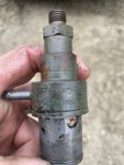
Looks like these pumps are a Delphi ? Maybe there was another manufacturer they used ?
 

Attachments

loosegravel

Just a retired mechanic who's having fun!
504
892
93
Location
Enumclaw, Washington
Looks like these pumps are a Delphi ? Maybe there was another manufacturer they used ?
Interesting. I wonder how many different IP's were used in these engines? To comment on one of your other posts, it's very common to see a little rust on these IP's. These units may sit unused for long periods of time. Condensation will prevail, especially in high humidity places. Like others have mentioned here, as long as you can manually depress the IP's in your hand that part should be good. The other part is the fuel control. It should move from stop to stop with not very much resistance.
 

Sidis8

Member
Steel Soldiers Supporter
47
47
18
Location
Nj
Interesting. I wonder how many different IP's were used in these engines? To comment on one of your other posts, it's very common to see a little rust on these IP's. These units may sit unused for long periods of time. Condensation will prevail, especially in high humidity places. Like others have mentioned here, as long as you can manually depress the IP's in your hand that part should be good. The other part is the fuel control. It should move from stop to stop with not very much resistance.
The fuel pumps work ok, when I press the spring, they pump out fuel.

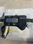
curiosity got the best of me lol, took out one of the known good pumps from #3, zip tied that shim pack together and measured it. 1 and 2 are no where close to this measurement. Somebody definitely messed with the shims. Gonna get a few new sets and make 1 and 2 the same thickness.

am I correct in assuming that since the shims are messed up on 1 and 2, this is causing over fueling on those cylinders ?
 

Attachments

Top
AdBlock Detected

We get it, advertisements are annoying!

Sure, ad-blocking software does a great job at blocking ads, but it also blocks useful features of our website like our supporting vendors. Their ads help keep Steel Soldiers going. Please consider disabling your ad blockers for the site. Thanks!

I've Disabled AdBlock
No Thanks