sigley89
Member
- 41
- 31
- 18
- Location
- Willow/Alaska
Back story. We have 2 803’s. One runs cherry the other has no crank.
We’ve been digging through the TM and running through the engine fails to crank troubleshoot. We have no power to the control panel. No lights or primer pumps running. What we have done so far:
ENGINE FAILS TO CRANK.
Step 1. Test for defective DEAD CRANK switch. (Tested for continuity in normal and crank position. We have continuity. Dead crank switch will not turn over engine with flipped to crank)
Step 2. Check for loose or corroded battery cable terminals or battery posts. (Good)
Step 3. Check that batteries are installed correctly
(Correct)
Step 5. Test for defective DC CONTROL POWER circuit breaker (fuse has continuity)
Step 6. Test for battery voltage at terminal 1 of starter solenoid. (Good voltage)
Step 7. Test for battery voltage at + terminal of starter solenoid with MASTER SWITCH in START position.
b. If battery voltage is not present, do Step 8.
( don’t remember if it was placed in start or not but no voltage)
Step 8. Test for battery voltage at input of MASTER SWITCH, refer to Electrical Schematic FO-1.
b. If battery voltage is not present, do Step 10.
(No voltage)
Step 9. Test MASTER SWITCH for output voltage in START position, refer to Electrical Schematic FO-1.
a. If battery voltage is present at MASTER SWITCH output temninal (7) and ground, do Step 13. b. If battery voltage is not present at output terminal, test MASTER SWITCH
( don’t remember if we did this or not. At this point we started comparing readings from the working genny to the no working one
Step 10. Test for defective battery charging ammeter shunt,
(Our reading is .8 ohms but so are the readings on the running genny. TM says needs to be below .5 ohms but the other genny has the same reading so we assumed it was good. Also checked for voltage and we have no power from the posts to a know good ground. The running genny shows 24v )
11. Test for defective Reverse Battery Diode (CR1),
TM says between 7-7.8 ohms for these but we couldn’t get more that 4 ohms on any of them. Running genny has same readings. **thinking my multimeter might be junk**
Step 12. Test for defective EMERGENCY STOP switch,
(No power to switch)
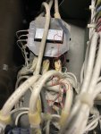
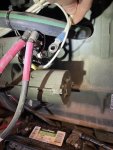
before we get too far is there anything simple we might have missed? Why are we not getting power to the control panel? No lights or anything.
Thanks for any help.
-Matt


