• Steel Soldiers now has a few new forums, read more about it at: New Munitions Forums!

  • Microsoft MSN, Live, Hotmail, Outlook email users may not be receiving emails. We are working to resolve this issue. Please add support@steelsoldiers.com to your trusted contacts.

Mep-803a produces no power

PETE01

New member
25
0
1
Location
Frederick, MD
Greetings from a Newbie. Been lurking around for a while and I've learned a great deal about MEP generators from your posts and comments.

I recently bought a MEP-803A from GL which did not have the circuit protection fuse. 2 diodes in the voltage regulator were burned out (now replaced) Phase to Neutral voltage is 19 VAC. Voltage phase to phase is 38 VAC.

After a multitude of tests, I've come to the conclusion that the Q1-Q2 winding is shorted. Voltage produced is approx 1 volt. Resistance hovers around .5 ohms when hot and 1.2 ohms when cold.

The stator, rotor, exiter stator, exiter rotor and rotating diodes all test out good. Stator windings I could see from the open back plate all look good. No burn marks, no brown paint.

I was thinking of replacing the voltage regulator with a universal voltage regulator, Power Tronics XR8 comes to mind. Rep says that their VR is powered with 120 volts from the stator, no need of the Q1-Q2 leads. Has anybody ever tried a similar approach? Your comments would be appreciated.

Also, if anybody knows the nominal exciter voltage for this unit, it would be appreciated.

The engine side of the generator is in great shape. 400 hours on a tier 2 reset. No smoke, no leaks, no knocking. Starts right up. What a gem! I love diesel engines, having owned diesel cars for many years. This small Lister Petter is a winner. These generators are very impressive machines!

Another plan would be to replace the stator assembly and possibly the voltage regulator. (I can't test my "repaired" VR so it might be necessary to get a new one). If anybody has good used parts in stock, please let me know.

Thanks for your help.

Pete
 

CT-Mike

New member
238
2
0
Location
CT
Have you downloaded the service manual and confirmed your winding is shorted out? Did you disconnect the leads to the winding to ensure you aren't reading across some parallel path? I would run through the tests called out in the manual before I started spending money. YMMV.

Mike
 

PETE01

New member
25
0
1
Location
Frederick, MD
Actually, I downloaded all of the manuals, Operation, Parts, Engine, 2, I believe and the technical manual and the technical bulletin. I read the technical manual cover to cover and then proceeded to troubleshoot the unit. I completed every test in the book, and I can put the results here if it would help. Bottom line, Quad winding resistance is way off and it does not produce any voltage. VR had burned up diodes which I have replaced. I also installed an inline fuse as per technical recommendations.

The generator does produce power when I flash the field. Voltage always goes back to O. That is the problem.

Pete
 

Hard Head

Member
Steel Soldiers Supporter
540
21
18
Location
Greenville SC
Actually, I downloaded all of the manuals, Operation, Parts, Engine, 2, I believe and the technical manual and the technical bulletin. I read the technical manual cover to cover and then proceeded to troubleshoot the unit. I completed every test in the book, and I can put the results here if it would help. Bottom line, Quad winding resistance is way off and it does not produce any voltage. VR had burned up diodes which I have replaced. I also installed an inline fuse as per technical recommendations.

The generator does produce power when I flash the field. Voltage always goes back to O. That is the problem.

Pete
quad_circuit.jpg
 

Hard Head

Member
Steel Soldiers Supporter
540
21
18
Location
Greenville SC
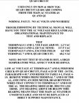
QUAD CIRCUIT


USED ONLY ON 5KW & 1OK"'W TQG QUAD CIRCUIT LEADS ARE COMING FROM THE MAIN AC STATOR AS
Ql AND Q2


• NORMAL FAULT: NO AC VOLTS AND NO HERTZ


TROUBLESHOOTING BY TECHNICAL MANUAL WILL HAVE YOU TEST IBE AC VOLTAGE REGULATOR (Al) ORGANIZATIONAL MAINTENANCE TO
TEST AND REPLACE


TEST
TERMINALS 1AND 2, VOLTAGE ADJUST: 1.2 VAC
TERMINALS 3 AND 4, 120 VAC SENSE: 117.5 VAC
TERMINALS 5 AND 6, EXCITER FIELD: 6.0 VDC
TERMINAL 7 AND 8, QUAD CIRCUIT: 68.2 VAC


NOTE: DO NOT TEST IF STATOR IS HOT, A HIGH
TEMPERATURE WILL AFFECT YOUR READINGS.


LOW AC VOLTAGE AT TERMINALS 7 AND 8, PERFORM CHECK ON QUAD CIRCUIT, PAGE 4-23 OF THE -24 TM, PARAGRAPH 4-10.7 AND REFER TO TABLE 4-1, PAGE 4- 19. REMOVE WIRES FROM TERMINAL 7 AND 8 OF THE Al, AND USING AN OHM METER, READ BETWEEN WIRES THAT CONNECT TO TERMINALS 7 AND 8 OF THE Al. THE READING SHOULD BE .9053 TO 1.224 OHMS. ANY READING ABOVE OR BELOW THIS READING MEANS THAT THE MAIN AC STATOR IS UNSERVICEABLE AND MUST BE REPLACED.

"MEP's are like a box of chocolates. You never know what you're gonna get."
 
Last edited:

PETE01

New member
25
0
1
Location
Frederick, MD
Thanks for sending the TB

I had found it on this site, I believe and first discarded it as it indicates that the condition is no volts no hertz. I have 20 volts and 60 cycles. Upon further investigation I realized that the condition described is exactly what is going on.

Burned diodes, no fuse, No volts and low resistance on quad winding. That is my problem.

So for now my solution is either get a new stator ($2,500) from Onan, rewind the stator ($975 quoted) or find a NOS unit. I went through the voltage regulator with a fine tooth comb and replaced the diodes, so I may be in good shape as far as this part goes. Otherwise I may need a new or used voltage regulator. This part seems really hard to find.

Looks like I'm slowly getting somewhere.
 

DieselAddict

Well-known member
Steel Soldiers Supporter
2,486
1,890
113
Location
Efland, NC
REMOVE WIRES FROM TERMINAL 7 AND 8 OF THE Al, AND USING AN OHM METER, READ BETWEEN WIRES THAT CONNECT TO TERMINALS 7 AND 8 OF THE Al. THE READING SHOULD BE .9053 TO 1.224 OHMS. ANY READING ABOVE OR BELOW THIS READING MEANS THAT THE MAIN AC STATOR IS UNSERVICEABLE AND MUST BE REPLACED.
PETE01 said:
After a multitude of tests, I've come to the conclusion that the Q1-Q2 winding is shorted. Voltage produced is approx 1 volt. Resistance hovers around .5 ohms when hot and 1.2 ohms when cold.
Just wanting to check and see if we were talking about the same thing in both of the quotes above. According to the manual if you are getting 1.2 ohms on the stator you are in spec. At the edge but still in spec.

Is the stator shorted to ground? If the resistance is OK can you run a HiPot test?
 

PETE01

New member
25
0
1
Location
Frederick, MD
Hi Chris. Thanks for your response. I've read your approx. 35 page thread on the MEP-831a. How interesting. I have two 831a gensets waiting for a minor overhaul. Just stared up one this weekend. Love these small Yanmar's! Mine started right up and purrs like a kitten.

I mis-stated the resistance reading on the Q1-Q2 winding (Leads connecting to Terminal 7 and 8 ohm reading on the leads (disconnected from the AVR) is .02 ohms. I did had a dead cold reading at 1.2 ohms which threw me off in the beginning of this troubleshooting excercise. In any case Q1-Q2 should produce 60 to 90 volts AC and it the reading I get is 1 volt. The quad winding is not shorted to ground. All of the main windings test in spec, none are shorted to ground and none are shorted to each other. I have 6 good stator windings.

The generator produces 19 VAC on each phase to neutral and phase to phase on all 3 phases is 39 VAC.

So it's pretty clear that I have a bad Q1-Q2 stator winding. The Military solution is to replace the stator, which i will probably do to keep this generator as close to stock as possible.

I'd have to take it to a shop for a hi-pot test.
 
Last edited:

Guyfang

Moderator
Staff member
Moderator
15,977
22,360
113
Location
Burgkunstadt, Germany
And why not just replace the Quad winding? Its a valid replacement part. I have replaced any number of them. Just make sure you use the right UOC. Look up the part number and NSN. Plug them into the web browser. See what happens. Cheaper then all the other solutions listed above. You could even get it rewound.
 

PETE01

New member
25
0
1
Location
Frederick, MD
The quad winding is embedded in the generator stator, Part # 220-4236-02. (Item 43 in the parts book page 24-1)

The excitor stator part #220-4265 (Item 11in the parts book page 24-1) connects to the F1-F2 terminal board which in turns is connecting to terminals 5 and 6 on the A1 voltage regulator. My tests show the excitor stator, excitor rotor, rotating rectifiers, generator rotor all within spec.

It would definitely be cheaper to replace the excitor stator, but I'm not sure it would solve my problem.

Thanks,
 
Last edited:

Guyfang

Moderator
Staff member
Moderator
15,977
22,360
113
Location
Burgkunstadt, Germany
For some reason I have confused the whole thing. I kept thinking excitor winding. But writing quad. Oh well no wonder my kids look at me funny sometimes.
 

mingram

Member
30
0
6
Location
boynton beach, florida
I need to test mine as the push to test on the ac interuppter is not lighting up. How is this test done, system powered up. or just in prime mode the tech manual is not clear. Any help appreciated
was refering to this test:
 
Last edited:

Guyfang

Moderator
Staff member
Moderator
15,977
22,360
113
Location
Burgkunstadt, Germany
There are three wires in the bottom of the light socket. With the S-1 in the run position, engine not running, one of the wires should have 24volts on it. Another wire should have a connection to ground. The third wire has voltage on it when th K-1 closes. So first see if you have voltage on the one wire. Sometimes they get broken off, or shorted when someone turns the light socket barrel to tighten the light socket instead of the locking nuts.
 

PETE01

New member
25
0
1
Location
Frederick, MD
The resistance readings are normally done with the generator turned off. The voltage measurements are made with the unit running.

Work safely!

Pete
 

Guyfang

Moderator
Staff member
Moderator
15,977
22,360
113
Location
Burgkunstadt, Germany
You do not need to run the set, to test the press to test function on the AC interrupter light. As long as the set is not running and S-1 is in any position other then off, the press to test function will work. It is a compleat different function then the K-1 closing its contacts and activating the AC interrupter light.
 

mingram

Member
30
0
6
Location
boynton beach, florida
Thanks Pete01. I don't believe I need to run this test "http://www.steelsoldiers.com/attachment.php?attachmentid=634061&d=1468836542&thumb=1"
now as the generator is working fine and provides my house power with no issues. Guyfang I will test for the 24 volts at the light it self now. The switch works fine and closes the generator circuit without an issue. Thanks for all the help.
 

PETE01

New member
25
0
1
Location
Frederick, MD
Good for you. Mine is still DOA. Stator is shot. Found a NOS replacement but its too hot to work on this project. I replaced all the diodes in the A1 regulator. A couple of them were all burned up.

Now I need to find an old electric stove to make a load bank tester. Sounds like a trip to Lowes white goods container...
 

Guyfang

Moderator
Staff member
Moderator
15,977
22,360
113
Location
Burgkunstadt, Germany
Mingram,

often, the K-1 contractor closes its contacts, and the contacts for the light do not work. You can pull the top cover and check them at the K-1, then trace the circuit back to the light. Start at the K-1.
 
Top