• Steel Soldiers now has a few new forums, read more about it at: New Munitions Forums!

  • Microsoft MSN, Live, Hotmail, Outlook email users may not be receiving emails. We are working to resolve this issue. Please add support@steelsoldiers.com to your trusted contacts.

Mep-803a produces no power

mingram

Member
30
0
6
Location
boynton beach, florida
There are three wires in the bottom of the light socket. With the S-1 in the run position, engine not running, one of the wires should have 24volts on it. Another wire should have a connection to ground. The third wire has voltage on it when th K-1 closes. So first see if you have voltage on the one wire. Sometimes they get broken off, or shorted when someone turns the light socket barrel to tighten the light socket instead of the locking nuts.
I have 24 dc volts on the third line.
 

kloppk

Well-known member
Steel Soldiers Supporter
1,976
3,095
113
Location
Pepperell, Massachusetts
Guyfang, okay i can't seem to find the K1. Is it located in the box below the convenience outlet box K8
m
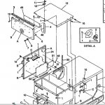
To get to K1 you have to remove the top cover item 13 below.
K1 is located behind the bulkhead that the voltage regulator, burden resistors etc are bolted to.

Top Cover K1.JPG

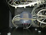
Once item 13 is removed look over on the left behind where the resistors are mounted and you will find K1.
The big black cube seen below.

20160108_111946.jpg
 

mingram

Member
30
0
6
Location
boynton beach, florida
To get to K1 you have to remove the top cover item 13 below.
K1 is located behind the bulkhead that the voltage regulator, burden resistors etc are bolted to.

View attachment 640836

Once item 13 is removed look over on the left behind where the resistors are mounted and you will find K1.
The big black cube seen below.

View attachment 640837
Okay yeah i know were that is it is behind the backboard, have to remove the top cover to get to it. I actually had that off last week to clean out all the dust that was back there. Thanks for the info. Guyfang actually said to remove the top cover but i skipped right over that.
m
 
Last edited:

zarathustra

Active member
Steel Soldiers Supporter
235
58
28
Location
glasgow,ky
The last voltage regulator I repaired had the diodes shorted, but ALSO had one bad FET transistor. I replaced both of the FET's. The 2 FET's are the large flat transistors that are glued to the heat sinks on either end of the regulator board. They can be tough to find, so if you have a problem getting them I have a few spares...

The generator is designed to generate a low AC signal even if the regulator is shut off (wire 8 disconnected if I remember correctly). If you get no AC at all when the regulator is off, then the stator is likely bad. If you can force it to generate electricity by holding S1 in the flash position then that shows that the stator will generate AC, but does not show if the Quad windings are OK or the VR is good.

It sorta works like this:
The VR does NOT receive any power from the 24 vdc circuitry. It receives an AC signal from the quad windings (they are a tiny "generator within a generator") and the output only feeds the regulator. The regulator has a rectifier that converts to DC and controls the VR unit. The VR feeds a DC signal to the exciter stator windings which then generates an AC signal in the exciter rotor. That AC signal is rectified through the rotating rectifier and the resultant DC signal is passed to the AC generator rotor which varies the AC voltage that is the output of the unit.

The VR does sample one of the legs of the generator as part of the feedback loop and takes that as an input to "decide" whether or not it needs to raise or lower the voltage to hold the output constant.

That seems like a lot of generating / rectifying etc, but it is the only way they could make a brushless generator.

Also, I believe it provides some fire protection for the unit in case the rotor goes banannas. The quad windings would fail and shut down the AC generating process. If the regulator got power from the 24 vdc circuits it would just keep telling the rotor to make more power in the case of a failure of the rotor. Even though these units seem to have a lot of wiring nonsense, they are actually pretty well designed. Now if they only didn't have a Lister Petter engine in 'em.....
 
Last edited:

PETE01

New member
25
0
1
Location
Frederick, MD
Update: Installed new stator. Generator now produces voltage on all 3 legs. GREAT.

With voltage potentiometer cranked up all the way I only get 190 volts across 2 legs. Frequency is good at 60 hertz. Voltage is stable.

I had changed the diodes in the voltage regulator.

Does anybody have any idea what is going on? Thanks for your help.

I am finally getting somewhere...
 

joshua1001

New member
24
0
0
Location
Simpsonville SC
mep1.jpgmep2.jpgIm thinking we have the same issue. Mine wasnt making any power and when I took the top panel off I found T1 through T12 unhooked. I hooked up everything and had 60hz but no volts on the meter. I checked my L1 and L3 voltage and was getting 36v on each. I came accross another thread where holding the start selector in the start position to long causes catasrophic damage to the avr and stator. This would be why my generator had good parts robbed with the bad crap finger tightened in place. It was getting dark so I didnt get to check the stator per the TM but ill do that tomorrow to confirm. Im just debating on if id want to try to save the unit or scrap it as a parts unit.
 
Last edited:

PETE01

New member
25
0
1
Location
Frederick, MD
I definitely had a bad stator. Q1 Q2 was burned to a crisp. I found a new old stock stator and it gave new life to my genset. I had replaced 2 diodes on the voltage regulator board which were fried.

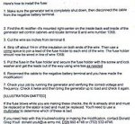
I also installed the fuse, I think that's what you were talking about in your response to make sure this doesn't happen again.

I'm pretty sure there is something else not working in the VR, I'll take it apart tomorrow. There is a small potentiometer on the VR board. Does anybody know what it does?

Voltage regulators are available NOS but they are a little pricey, about $300.
 

joshua1001

New member
24
0
0
Location
Simpsonville SC
I dont know what the potentiometer does but it does have a marking on mine with red to show if its been tampered with. where did you find your stator, I havnt found a source yet.
 

joshua1001

New member
24
0
0
Location
Simpsonville SC
have you thought about replacing the fet transistors like mentioned above. after reading his post id be tempted to replace the resistors and fet,s while in there.
 

PETE01

New member
25
0
1
Location
Frederick, MD
There was a guy on ebay selling stators for the smaller 802A. On one of the pictures he posted I recognized the part number for the stator for the 803A. I contacted him to confirm and ended up making a deal with him for $450 shipped.

I had found a rewinding shop in California who wanted $900 plus shipping both ways, so I saved a bundle. I contacted a local shop and they quoted $thousands. They were just not interested.

These generators are great. Parts are hard to find.
 

PETE01

New member
25
0
1
Location
Frederick, MD
Is there any way to determine if the FET Transistors are bad? Can they be tested? They both looked good when I did the diode repair, but I'm not sure I would know a good one from a bad one.
 

PETE01

New member
25
0
1
Location
Frederick, MD
The troubleshooting guide in the Technical Manual is really good for the fried Quad windings problem. Resistance accross Q1 and Q2 is supposed to be .9053 to 1.224 Ohms. My reading was .02 which indicated a problem. When I removed the stator, I could see there was a section of the winding on the engine side of the stator, that were all burned out. Even though the other windings were in spec, there was enough damage to warrant the replacement of the stator.

Swapping out the stator is not a difficult job. The TM essentially says to dismantle the whole unit. I was able to slide it out of the front of the unit by taking out the lug board and the doors. I made some sleepers out of some 2 x 4's and slid out the stator after jacking up the engine a bit and setting a block to carry the weight of the engine and the rotor.
 
Top