• Steel Soldiers now has a few new forums, read more about it at: New Munitions Forums!

  • Microsoft MSN, Live, Hotmail, Outlook email users may not be receiving emails. We are working to resolve this issue. Please add support@steelsoldiers.com to your trusted contacts.

MEP-803A Will no longer start seems to be fuel issue not sure how.

kloppk

Well-known member
Steel Soldiers Supporter
2,135
3,506
113
Location
Pepperell, Massachusetts
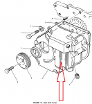
He needs to remove the Gear End Cover over the governor. This..
1722802778389.png

The TM calls out to insert a screwdriver through a hole in the flywheel housing to get to the ring gear (to keep the crankshaft from turning while removing bolt 5 above.)

There doesn't seem to be a hole in the flywheel housing to do this.
 

2Pbfeet

Well-known member
425
758
93
Location
Mt. Hamilton, CA
He needs to remove the Gear End Cover over the governor. This..
View attachment 929049

The TM calls out to insert a screwdriver through a hole in the flywheel housing to get to the ring gear (to keep the crankshaft from turning while removing bolt 5 above.)

There doesn't seem to be a hole in the flywheel housing to do this.
Two thoughts;
Is there a drain hole at the bottom of the flywheel assembly? (I'm not near mine to check.)
I've never attempted it, but wouldn't inserting a screwdriver into the generator head fan serve the same purpose of locking the crankshaft?

All the best,

2Pbfeet
 

Guyfang

Moderator
Staff member
Moderator
16,701
23,937
113
Location
Burgkunstadt, Germany
02.32.1 Removing the End Cover
1. Fit the flywheel locking tool, 317-50057, into the
flywheel gear ring by screwing it into the tapped
hole in the flywheel housing.


Figure 2.32.1 Fitting the Flywheel Locking Tool
2. Ensure the locking tool is fully engaged into a
flywheel ring gear tooth by attempting to turn the
flywheel.
If the locking tool is not available wedge the
crankshaft with a suitable piece of hardwood to
prevent it turning.

(The attachment shows the hole.)


3. Slacken the alternator, or belt tensioner, and move
it towards the crankcase sufficiently to allow
removal of the fan drive belt.
 

Attachments

deherenman

Member
44
25
18
Location
Texas
Terrific I'll give it a go when I have the proper socket. Where what TM is this located in? Or is this from an onan's manual?
 

deherenman

Member
44
25
18
Location
Texas
So have you had the gear and cover off? And do you have to remove the radiator to get enough clearance to remove the bolt out of the serpentine pulley? Because it seems like a really tight fit.
 

Light in the Dark

Well-known member
Steel Soldiers Supporter
3,813
5,889
113
Location
MA
You are going to wish you did remove the end of the machine. If you remove the (2) plastic fan guards, and unbolt all of the bolts along the lower edge of the whole rear sheet metal assembly (engine bay, and hidden to either side of the fuel tank... gotta pull that panel), after the radiator is drained and the hoses undone from the water pump, you can take the whole end off in one piece carefully.
 

Guyfang

Moderator
Staff member
Moderator
16,701
23,937
113
Location
Burgkunstadt, Germany
I will add something here. If you do not pull the front end off, and its not that hard, your chances of screwing up something else, is much higher. And I can assure you, if you don't pull it off, your blood pressure will get load tested. The very first time I tried it, without pulling the front end, fixed me for life.
 

2Pbfeet

Well-known member
425
758
93
Location
Mt. Hamilton, CA
02.32.1 Removing the End Cover
1. Fit the flywheel locking tool, 317-50057, into the
flywheel gear ring by screwing it into the tapped
hole in the flywheel housing.


Figure 2.32.1 Fitting the Flywheel Locking Tool
2. Ensure the locking tool is fully engaged into a
flywheel ring gear tooth by attempting to turn the
flywheel.
If the locking tool is not available wedge the
crankshaft with a suitable piece of hardwood to
prevent it turning.

(The attachment shows the hole.)


3. Slacken the alternator, or belt tensioner, and move
it towards the crankcase sufficiently to allow
removal of the fan drive belt.
@Guyfang, that looks really helpful, but that flywheel enclosure doesn't seem to match mine, so I am probably doing something stupid. That hole would seem to me to be nominally 120 / 240 degrees from the starter, according to that very clear and helpful diagram.


All the best,

2Pbfeet
 

fb40dash5

Active member
Steel Soldiers Supporter
102
159
43
Location
MD
A couple random thoughts. First, if you really wanted to avoid finding a way to lock the flywheel, check out a "crankshaft bolt tool", part # SP70865 for example... kinda works like a crowsfoot, but instead of turning it with a ratchet, you smash it with a hammer. Works great for crank pulleys mashed much closer to things than this.

Second, pulling the starter is easy. Mine came with the diesel preheater, which uses a nipple-turned-freeze-plug kinda behind the starter. I ended up popping my starter off to reinstall a freeze plug, took all of a couple minutes.

And finally, you might do well to consider the advice to just do the "extra" work to disassemble it more than you want to. I'm the master of spending way too much time trying to not do "extra" work... maybe one day I'll fully break myself of it. So much time wasted going "if I could just..." instead of just ripping what's in the way out of the way....
 
Last edited:

deherenman

Member
44
25
18
Location
Texas
I will have to look and see what my options are. At this point in time the unit is not in an enclosed space and pulling the front end off might be a tall order since I don't have a way to cover it back up with out putting the covers back on and covering with some heavy plastic. I don't have a way to move the unit I had it dropped from delivery lift gate truck right where it is sitting behind the barn. Now that seems short sighted didn't think I was going to have to dive into the engine at the time. I will have to see what I can do about getting it inside. Might be easier to build a tent with some 2by4s to keep it out of the weather since I will not be able to do this job/ repair in 4-6 hours.

Thanks every one for tips / help on these issues.
 

Ray70

Well-known member
2,580
5,854
113
Location
West greenwich/RI
So I fixed the linkage issue had the little nut in the wrong spot preventing the linkage to move freely.
Now for the racing engine it would stop on it own still running crazy fast after fixing linkage. So I rotated the fuel pumps.
After rotating the a small amount. The unit starts vary slow and will not get up enough RPM's to stay at 60 HZ before slowing down to a vary slow chug pace. When it was racing and when it is running slow RPM it is blowing black smoke heavy. Unit use to only puff a little black smoke at startup.

Any one in the DFW area that could take a look?
You should first rotate all the pumps counter clockwise until the fuel inlet lines are all touching against the pushrod tubes.
Then remove the fuel pump solenoid linkage again. The lever should automatically spring forward ( towards the generator head )
If it stays to the left then your rack is still sticking.
You can also remove one of the pumps and stick your finger down the hole and feel the notch in the rack where the pump pin fits.
You can also get in there with a small USB borescope camera to see the pin on the adjacent pump.
I have a suspicion that your issues is a pin not correctly engaged in the rack, causing the rack to bind up.
When all 4 pumps were out did you happen to check the rack movement? And when reinstalling the pumps did you have to hold the rack forward with the lever to get the slots into position under the metering pump holes?
 

deherenman

Member
44
25
18
Location
Texas
Detailed method for installing the pumps.

So once all of the pumps are out. And the rack would still be stuck in position. It would not spring forward. So after I'm sticking the rack with my finger. It would pop loose it would move freely.

Then to put the pumps back in. I would take an allen wrench that is the same size as the pen on the pump slide it in to the rack when the rack is all the way forward in position I move the rack forward with my finger. And that would hold the rack in place now for the other three pumps I would take the pin on the pump move it all the way forward to the left as well as rotating the pump where the fuel Barb was all the way forward to the left and drop it in to the rack while still keeping the front cylinder and the rack held with the Allen wrench to where everything wouldn't move. I did that for the remaining three pumps. Then I would remove the Allen wrench out of the rack from the closest cylinder to the radiator and drop that last pump in. I would then tighten down each pump after putting the fuel line on the top so it was kind of compressing the spring on the IP. I left the Barb turned where the barbs were between the post for holding the racks down and the cylinder head but pointing towards the right to where I could still get the fuel line on and it wasn't pressing it towards the engine. with all shims and place with their original cylinders.

I would then tighten the IP's down tighten the remaining fuel line to where there was no leaks. I can then reconnect the linkage to the solenoid. And to test this to make sure that my IPS are installed correctly. I can fire up the unit it'll start no issues doesn't start slow fires right up after priming . Once the unit is running I would adjust the idle with the idle adjustment on the left hand side of the unit the unit will idle up and down with that adjustment with no excessive smoke other than just at startup.

I did get a USB 5.5 mm camera and inserted it down one of the IP holes as I was inserting the pumps. I couldn't tell mostly because I have poor eyesight if the pens were in the correct position or not but I think it proves my point that it'll idle up and down correctly. The issue I have is once the rack goes in the forwards position it gets bound up or if I put pressure on it from the IPS after the initial startup it sticks.

Another issue I have is when I move the shut off lever on the side of the engine let's say the lever is all the way towards the right. And I'm turning it towards the left about 2/3 of the way towards the left it will pop or have a little hiccup and it'll cause that rack on the inside to jiggle up and down and it'll make a little click and then I can continue turning the rack all the way to the left all the way into forwards position and then when I go to release the rack it'll only release about an eighth or a fourth of the way towards the right. And if I stick my finger in one of the IP holes in jiggle it it's stuck it only has that quarter of an inch to 8 in of play. Now if I kind of push on it a little bit it'll pop loose and then I can move it the full inch and a quarter amount with no IPS in. That's why I think I probably need to investigate further by taking the end cap off. I am welcome to suggestions I've tried to describe my issue in as much detail as possible. If anybody wants to do a troubleshooting phone video call. 765. 780. 2428
 

Guyfang

Moderator
Staff member
Moderator
16,701
23,937
113
Location
Burgkunstadt, Germany
@Guyfang, that looks really helpful, but that flywheel enclosure doesn't seem to match mine, so I am probably doing something stupid. That hole would seem to me to be nominally 120 / 240 degrees from the starter, according to that very clear and helpful diagram.


All the best,

2Pbfeet

Well, if it were me, and I did not want to pull the front end, I would pull out the Mag Pickup and jam a wooden dowel in there to hold the flywheel in on spot.
 

Light in the Dark

Well-known member
Steel Soldiers Supporter
3,813
5,889
113
Location
MA
Or wedge the flywheel through the exterior metal lattice thats visible in that photo above, at multiple locations. But if you are not rotating the crank (which with the drive pulley and belt off, little chance of that) and only pulling the cover to articulate the FSS armature, the timing should stay intact and it not be needed IMO.
 

deherenman

Member
44
25
18
Location
Texas
I'm going to have to see if I can even break the loose the bolt. At this point using a 15/16 wrench using the box and and a pipe I only get a very small amount of movement not enough to actually break it loose and I'm not sure that I can get a impact tool in there without removing the radiator. Unfortunately I don't have a breaker bar. And I don't have a shallow impact socket. So it looks like removing the end might be the best solution although if I get a shallow socket and a breaker bar maybe I can at least get her loosened up. The dash 24 TM says that that hole is on there at 225 ft pounds of torque. And if the water separator is any indication King Kong probably put that thing in there and that's probably more like 350 or 400 lbs.
 
Top