• Steel Soldiers now has a few new forums, read more about it at: New Munitions Forums!

  • Microsoft MSN, Live, Hotmail, Outlook email users may not be receiving emails. We are working to resolve this issue. Please add support@steelsoldiers.com to your trusted contacts.

MEP 803A will not turn on?

Guyfang

Moderator
Staff member
Moderator
16,777
24,103
113
Location
Burgkunstadt, Germany
People, I have worked on gen sets more or less since 1972. In that time, I have seen maybe, maybe, maybe, one bad switch for turning on and off the load contactor. I have seen many miswired, but that's about it. I wish I could take that paragraph out of the troubleshooting diagram, that tells you to check the switch. Go to post 34. Start there, with the wire diagram and schematic. Read what Kloppk wrote. Ignore any referance to S5, you have checked it, replaced it and if you wired it back up right, that takes it out of the equation. Dosnt leave much to check.
 

jwb1986

New member
15
0
1
Location
IN
Been working on the gen. The push to test lights work fine. The K1 will still not stay closed unless you hold the s5 switch in closed position. I have checked the pins of both DS6 and 7. I have 24v when s1 is on and I have ground. What I am finding that has me stumped is this.... Pin 2 is showing 24v all the time, but when you hold s5 closed, pin 2 goes to zero. Also,I have found that when the battle short is on, then the AC interrupt switch and k1 work as they should. I then have a constant green light for the AC interrupt and I get power to the output lugs.
 

kloppk

Well-known member
Steel Soldiers Supporter
2,145
3,526
113
Location
Pepperell, Massachusetts
.... I have checked the pins of both DS6 and 7. I have 24v when s1 is on and I have ground. ...
Pin 2 on DS7 is behaving as it should.

... Also, I have found that when the battle short is on, then the AC interrupt switch and k1 work as they should. I then have a constant green light for the AC interrupt and I get power to the output lugs.
With Battle Short ON this bypasses the Overload section of the K8 relay so it's behaving as if there was an overload detected by K8.
Looks like either an issue with K8, wiring to K8, or wiring and/or components that send signals to K8 such as Burden resistors, current transformer, etc.
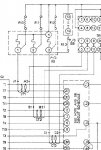
Time to take a close look at the schematic near the end of the -24 TM.

Does the Overload Fault light come on when it drops power to the lugs?
 

Guyfang

Moderator
Staff member
Moderator
16,777
24,103
113
Location
Burgkunstadt, Germany
People, I have worked on gen sets more or less since 1972. In that time, I have seen maybe, maybe, maybe, one bad switch for turning on and off the load contactor. I have seen many miswired, but that's about it. I wish I could take that paragraph out of the troubleshooting diagram, that tells you to check the switch. Go to post 34. Start there, with the wire diagram and schematic. Read what Kloppk wrote. Ignore any referance to S5, you have checked it, replaced it and if you wired it back up right, that takes it out of the equation. Dosnt leave much to check.
Below is post 34

Here is a description of the latching circuit I did a while back...

It's a latching circuit created byK1, S5, CR3 & K8.

After the engine starts and oil pressure is up K20 closes and K1 terminal X has 24 volts supplied to it. When you toggle S5 to CLOSE S5 terminals 5 & 6 connect momentarily connecting K1 terminal Y to ground causing K1 to close and closing K1 contacts 11 & 12. When you release S5 a path from K1 terminal Y to ground is created via S5 terminal 5, CR 3, S5 terminal 2, S5 Terminal 3, K8 OL, K8 SC, to K1 terminal 11, to K1 terminal 12 to ground. This path keeps K1 activated after releasing S5 from the CLOSE position.
When you toggle S5 to OPEN you break the connection between S5 terminal 2 and S5 terminal 3 breaking the ground path causing K1 to open.

K8 OL and K8 SC are in the path so that if the fault logic detects an overload or a short circuit condition is will cause K1 to open removing power from the lugs.

The lights have nothing to do with it. Look at post 34. You know its not K1. You know its not S5. Its not the lights. They have nothing to do with the function of K1. If it runs on battle shot, its only something in the safety chain. Kloppk asked you if the Idiot light came on, when you hold up the S5. I will ask you, did ANY idiot come on when you ran it on battle short? Something to try, is this. Take a wire and two roach clips and jump first the over voltage contacts on K8. start the set up, normally, and see if it works. If it works, K8 is bad. If it doesn't work, then shut it down, and use another wire and roach clips to jump the short circuit contacts. Test it again. If it works, K8 is bad.
 

jwb1986

New member
15
0
1
Location
IN
When I run the gen with battle short on, there is NO idiot lights on anywhere. Everything looks normal at that time.

Which numbers on the k8 do I hook my jumper wire to? I didn't want to mess anything up without asking.
 

Guyfang

Moderator
Staff member
Moderator
16,777
24,103
113
Location
Burgkunstadt, Germany
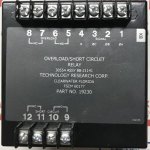
Correct me if I am wrong, but on the cover of the K8 relay, the contacts are printed on the cover. Not just the terminals, but the contacts also. Terminals 1 and 6 are AC input, if I remember correctly. You can start there. Start the set. Measure between terminals 1 and 6. You should have AC voltage. 120 volts. No volts? relay cant work. Find out why there is no volts. The rest of the terminals are labeled, with the contacts, N/O, normally open, and N/C, normally closed look at the wire schematic and find the right contacts. I would look for you, but a phone is not made to do that, and I am not home.
 

jwb1986

New member
15
0
1
Location
IN
Measuring between terminals 1 and 6 with a test lead on each terminal at same time, I get approx 5.5 volts. I also checked my second gen set that works fine and got approx the same reading.

How do I attach a pic on here?
 

kloppk

Well-known member
Steel Soldiers Supporter
2,145
3,526
113
Location
Pepperell, Massachusetts
How do I attach a pic on here?
After you start to compose a post or reply click on the "Go Advanced" button in the lower right.
You should then see more option buttons at the top of the text entry box.
Click on the one to the right of the two blue globes.
You will then get a dialog box so you can navigate to and upload your picture.

Being a new member of SS with only a few posts it may not let you upload pics until you achieve so many posts.
Give it a try though.
 

Guyfang

Moderator
Staff member
Moderator
16,777
24,103
113
Location
Burgkunstadt, Germany
Measuring between terminals 1 and 6 with a test lead on each terminal at same time, I get approx 5.5 volts. I also checked my second gen set that works fine and got approx the same reading.

How do I attach a pic on here?
I apologize for telling you to measure 120 volts between pins 1 and 2. I am not at home and cant look at my TM's and was shooting from memory. Not good. The only difference between my brain and Swiss cheese is that the holes are smaller in the cheese.
 

kloppk

Well-known member
Steel Soldiers Supporter
2,145
3,526
113
Location
Pepperell, Massachusetts
I'd suggest first checking the connections from K8 to the S7 the Battle Short switch.
Check the following with the genset OFF and Battle Short OFF.

K8 terminal 8 should be connected to S7 terminal 6. Check for continuity between these two points. ~ 0 ohms
K8 terminal 7 should be connected to S7 terminal 5. Check for continuity between these two points. ~ 0 ohms
Now check for continuity between K8 terminal 8 and K8 terminal 7. There should be continuity. ~ 0 ohms

If all that checks out good then I'd suggest starting the set with Battle Short ON and reading the following AC voltages and reporting back
- K8 terminal 1 to K8 terminal 4
- K8 terminal 2 to K8 terminal 4
- K8 terminal 3 to K8 terminal 4
 
Last edited:

jwb1986

New member
15
0
1
Location
IN
Thank you for the excellent info. I am fairly new at troubleshooting the electrical side of these gen sets but I'm determined to not give up. I will try to do some testing tomorrow sometime. Been fighting the flu.
 

jwb1986

New member
15
0
1
Location
IN
Ok just did the test that kloppk suggested.
Here is what I found:
NO continuity between K8 terminal 8 and terminal 7.

I stopped after finding this, assuming this must be where the problem is.
 

jwb1986

New member
15
0
1
Location
IN
That was with all power off. I did not unhook any wires. Only tested them as they were.

I tested my second (good) generator and it is testing exactly as kloppk said above.

So, do I have a bad k8?
 

Guyfang

Moderator
Staff member
Moderator
16,777
24,103
113
Location
Burgkunstadt, Germany
If you do not have continuity between pins 7 and 8, yes its bad. Now, try this. Hook a wire between pins 7 and 8. Fire it up, and see if it works. Its bed time for this old soldier. Also, test the other contacts first. Disconnect the wires. ALWAYS disconnect the wires, before testing continuity.
 

jwb1986

New member
15
0
1
Location
IN
Just tested it.
After hooking a jumper wire to the k8 terminals 7 and terminal 8, the gen set works great!
So my k8 must be bad inside.
 
Top
AdBlock Detected

We get it, advertisements are annoying!

Sure, ad-blocking software does a great job at blocking ads, but it also blocks useful features of our website like our supporting vendors. Their ads help keep Steel Soldiers going. Please consider disabling your ad blockers for the site. Thanks!

I've Disabled AdBlock
No Thanks