Evvy,
Reflecting on this missing lock washer issue and the explosion drawing of the 400 Hz Assembly, I would like to point out the following:
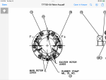
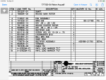
The Disk #44 is a composite of
1 Disks Part # B-718817-01
3 Disk Part # B-718930-01
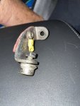
those are held together with lock washer #30 and Machine Screw # 31 to Brackets # 43
the diodes itself are screwed to bracket # 43 with lock washer # 30 and Nut # 33
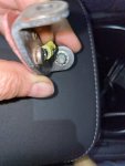
sofar so good, now do you know or can you tell us if the lock washer #30 was used on Diodes? Or did your assembly have no lock washers # 30 and or # 38 at all?
The lock washer # 30 with machine screw # 31 which secure the bracket # 43 to theFiberglass rings are the tricky ones when assembling this Diode Ring.
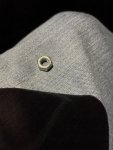
If you torque machine screw # 31 to high then lock washer #30 will grind its teeth to far into the first disk.
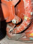
This lock washer then will act as a grinder on the first fiberglass ring.
Conclusion:
The machine screws # 31 have to be torqued to a specific value so lock washer # 30 doesn’t damage the first fiberglass ring but still locks everything together under vibration.
Without any lock washer, the results are pretty clear.
Maybe you can sweet talk Marathon to tell you to what torque these machine screws should be torqued to when using the lock washer # 30?
View attachment 879133
View attachment 879134
View attachment 879135
Peter