SLTRAM98
Member
- 32
- 27
- 18
- Location
- North Carolina
I have an 804a Genset, 164 hrs. on the clock. New to me (2006 make); here is the run down and trouble shooting to date.
1) Fresh batteries, when using the dead crank switch (on side of engine compartment), engine cranks totally fine, no issues.
2) When S1 (Master Switch) is turned to start, you can hear the shutoff solenoid open, but no crank.
3) Pulled Magnetic Pick Up (MPU) it did have some metal shavings but in great shape, cleaned it put it back in.
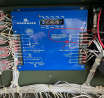
3) Read through the TM, traced things back to poles 18, 19 and 20 on A5 Governor Control board.
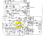
- Tested Poles per the test scenario's in TM, 18 to 19 'should be' normally closed when genset is off, but they are not. Note: I did notice a difference from the TM schematic which shows reversed NO and NC switches from the white markings on the GC A5 Board, appears to me that the A5 white markings are correct when genset is off, I guess the TM switch confi. would be accurate when the machine is running.
- Pulled A5 board out, its spotless, no burns, I do understand that only means so much but was looking for a blown up part, nothing.
- I JUMPED 18-19 poles to test my theory that their is a failed NC (normally closed) switch and genset STARTED right up, purred like new using S1 (Master Switch), ran no problem. I only let it run for a minute since I am not sure about the following items noted below.
- In the manual the wire diagram shows S14, but again reading on this forum, sounds like S14 is built into A5? (Please confirm this.)
- Am I correct in my understanding that the purpose of NC 18-19 switch relay at start up, which then should open after genset starts, is to protect the starter from getting hit again and grinding the starter? Eg; what happens if I cant solve S14 (built into A5) and install a wire jumper permanently?
- Does anyone have the A5 board schematic - specific to A5 - so I can see what else is driven by poles 18 and 19?
- Only other item I can see that 'may have' failed would be CR4, HOWEVER, it would stop power from getting to 18 so my jumper wire would not work regardless, so pretty sure that has NOT failed.
- I could install an external relay that is NC until startup, that would be pretty simple however, again I would like to know if anyone knows what else A5 is reading from the 18 and 19 poles. If no objection a permanent jumper would be nice.
Thank you for the help!


Attachments
-
309.3 KB Views: 1

