• Steel Soldiers now has a few new forums, read more about it at: New Munitions Forums!

  • Microsoft MSN, Live, Hotmail, Outlook email users may not be receiving emails. We are working to resolve this issue. Please add support@steelsoldiers.com to your trusted contacts.

MEP-804A Shutdown on Under Voltage, now won’t start

Jdj211

New member
11
15
3
Location
Houston, TX
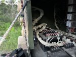
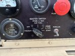
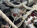
Hello, I just got an MEP-804A and after giving it a once over, I started it up. It ran for about 60 seconds before it shut down. The “under voltage” light was lit. I turned the master switch to the off position, then back to prime & run, then hit the button to test/reset the fault lamps. When I try to start it again, it will crank but won’t start. I did put in about 3 gallons of fresh diesel prior to starting it, and the gauge is reporting about 1/4 tank. While it was running it was under no load and the AC contractor was not closed.

I searched for under voltage in the TM’s and only found a basic procedure to verify battery voltage. The batteries are both brand new and fully charged. I’m reading 25.1VDC across them. Is there somewhere else in the control panel I should verify this?

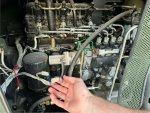
I’m thinking perhaps the under voltage was more of a symptom than a cause of my issue. My uneducated best assumption is that the engine isn’t getting fuel for some reason. I am not a mechanic so I wanted to check with the experts before I make things worse.

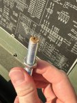
My next thought was to see if somehow there is air in the fuel lines but I’m not exactly sure how to verify or correct that. I’m sure it’s in the manuals, and I am searching through them currently.
 

Guyfang

Moderator
Staff member
Moderator
16,130
22,773
113
Location
Burgkunstadt, Germany
Apply 24 VDC to the electric actuator.
1719073550880.png

Take the J10/P10 apart. apply 24 VDC to J10 pins. Hold it there, you should hear/feel it click. Hold it there, have someone else turn the set over. If it starts and starts to run up, remove the 24 VDC from J10.
 

Jdj211

New member
11
15
3
Location
Houston, TX
Apply 24 VDC to the electric actuator.
View attachment 926209

Take the J10/P10 apart. apply 24 VDC to J10 pins. Hold it there, you should hear/feel it click. Hold it there, have someone else turn the set over. If it starts and starts to run up, remove the 24 VDC from J10.
Forgive the basic question, but I am still getting used to reading the schematics. Do you mean apply the 24VDC to the pins connected directly to the actuator (marked blue in my picture)? I was thinking that was P10. I’m not sure how to determine polarity for the wires A6-1 and A6-2. I’d rather not break something with the guess and check method.IMG_9750.jpeg
 

Jdj211

New member
11
15
3
Location
Houston, TX
I opened the cap (green in my picture) per suggestion from the guy I bought it from. It looked dry in there so I figured I wasn’t getting fuel. He suggested turned the engine over to see if I can see the rod move in there. I hit the dead crank and nothing moved. But I’m thinking maybe he meant turn the master switch to start, so I’m not sure the rod should have moved on a dead crank.

I opened the bleeder screw (red in my picture) and pumped the primer to get fuel into the injection pump. At first no fuel, then after a few presses I had fuel coming out. With the screw still cracked I hit the dead crank and fuel came out.

At this point I was going to try starting it again thinking maybe I bled the air out of the fuel lines. But I noticed the panel lights wouldn’t come on, and no fault lights when hitting the test. Needless to say it wouldn’t crank from the master switch. I verified 24.6VDC at the batteries. I need to check the schematics to see where that battery voltage should be coming in the control panel.
 

Attachments

Jdj211

New member
11
15
3
Location
Houston, TX
I opened the cap (green in my picture) per suggestion from the guy I bought it from. It looked dry in there so I figured I wasn’t getting fuel. He suggested turned the engine over to see if I can see the rod move in there. I hit the dead crank and nothing moved. But I’m thinking maybe he meant turn the master switch to start, so I’m not sure the rod should have moved on a dead crank.

I opened the bleeder screw (red in my picture) and pumped the primer to get fuel into the injection pump. At first no fuel, then after a few presses I had fuel coming out. With the screw still cracked I hit the dead crank and fuel came out.

At this point I was going to try starting it again thinking maybe I bled the air out of the fuel lines. But I noticed the panel lights wouldn’t come on, and no fault lights when hitting the test. Needless to say it wouldn’t crank from the master switch. I verified 24.6VDC at the batteries. I need to check the schematics to see where that battery voltage should be coming in the control panel.
UPDATE: The heat must have been getting to me yesterday. I had mistakenly left the dead crank switch in the off position. That was why I had no DC power at the control panel.

I tried starting the unit and it actually got some fuel and ran for about 15 seconds before shutting down again.

I will try applying 24VDC directly to the actuator when I have someone else to crank the unit with me.
 

Jdj211

New member
11
15
3
Location
Houston, TX
Apply 24 VDC to the electric actuator.
View attachment 926209

Take the J10/P10 apart. apply 24 VDC to J10 pins. Hold it there, you should hear/feel it click. Hold it there, have someone else turn the set over. If it starts and starts to run up, remove the 24 VDC from J10.
When applying 24VDC to the A6 pins I heard a click. And again when removing power. I opened the large hex plug view port and did the same test. I have as able to see the shaft move.

I also verified the other side of the plug was sending 24VDC when turning the master switch to start.

After some more searching on here I found that the MPU can be problematic. I saw that the resistance should be 900-1200ohms. Mine was reading 800. When cranking the unit, I got 5.5VAC.

I pulled the unit found it had a lot of debris on it. After cleaning it and reinstalling I was getting 1.8-2.2VAC. I saw in another post to aim for 3VAC. No matter where I adjusted the MPU, it would never get about 2.2VAC, almost always less than 2VAC. It is still reading 800ohm across the leads and at the control panel. They are only $20 so I ordered a replacement. I figure it doesn’t hurt to have an extra on hand anyway.
 

Attachments

Top
AdBlock Detected

We get it, advertisements are annoying!

Sure, ad-blocking software does a great job at blocking ads, but it also blocks useful features of our website like our supporting vendors. Their ads help keep Steel Soldiers going. Please consider disabling your ad blockers for the site. Thanks!

I've Disabled AdBlock
No Thanks