• Steel Soldiers now has a few new forums, read more about it at: New Munitions Forums!

  • Microsoft MSN, Live, Hotmail, Outlook email users may not be receiving emails. We are working to resolve this issue. Please add support@steelsoldiers.com to your trusted contacts.

MEP 805A Gen. NO Voltage

Capt.Moondog

Member
Steel Soldiers Supporter
61
42
18
Location
Walnut Hill, Florida
Afternoon
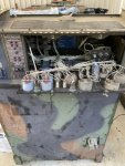
I’m new here and just bought this Gen. It was supposed to be ready to go after all fluids changed it had not run in 2 years supposedly.

I posted earlier this morning because I could not figure out why my Master switch would not crank on the normal setting and would crank in the Aux fuel and only stay running in that position.
after all afternoon of chasing rabbit trails and a member suggested a switch stuck I finally figured out previous owner changed Master switch and hooked everything up wrong😤

A little back ground when I first cranked it after a total fluid change I noticed the governor zipped tied so I unhooked it and throttle so it would not crank wide open when started after 2 years so the machine just idled for about 10 minutes then I ran it up a little all the while checking tempt etc… the voltage was around 240-250 ran a fan on the outlets.
Due to the governor being not hooked up and me trying to figure out why the switch wasn’t working right and all the cranking and messing around my under voltage light is on and nothing is reading in any of the gauges on outside😤
So been trying to go through manual and figure out how to self diagnose the problem I’m a whipped dog! Yes I hooked everything back up and governor seems to work but I think I might have over speed the Gen. And since the wires weren’t hooked up right the over speed never shut it off and I fried something the voltage regulator is $600-700 on eBay not sure what parts to start buying first! I live near Pensacola, Fl and Mobile, Al if anyone is near I’ll pay for some help! If you go to my account I have the first post there detailing my first set of problems

thanks for any help
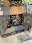
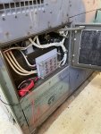
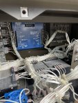
C8C12608-1110-470C-A5C5-617191E35F1A.jpeg37F03849-C37E-4064-AF1D-4517BA63A2E2.jpegB3C19C0D-D702-415F-A783-08C7B6C39EDA.jpeg
 

kloppk

Well-known member
Steel Soldiers Supporter
2,145
3,526
113
Location
Pepperell, Massachusetts
Have you downloaded the -24 TM? It has a test procedure for the AC voltage regulator in it.
The set was built with one two voltage regulator systems. TRC or Libby. Be sure to use the correct test procedure in the TM.
 

Capt.Moondog

Member
Steel Soldiers Supporter
61
42
18
Location
Walnut Hill, Florida
I will double check which manual I was using but was attempting to follow the steps it had me starting out checking the Governor control unit which I think is A5 which if I did right had juice to 1,3,5 while until was running but wasn’t sure if I was supposed to have a relay so it wouldn’t crank when turning S1 to start position during check then on to the voltage regulator post 10&11 do not have any juice while unit is running. I’ll try reading more but my brain became foggy been working on this thing all day

FF6AF12D-E284-4678-B5C8-731B01CB9B0D.jpeg
 

Guyfang

Moderator
Staff member
Moderator
16,755
24,065
113
Location
Burgkunstadt, Germany
You have two threads started that more or less are the same problem, same gen set. Please decide what one you want to keep. and tell me. Because I will delete the other.

KLOPPK is also someone who can help with a new or repaired VR. Kurt, have you read the other thread?
 

kloppk

Well-known member
Steel Soldiers Supporter
2,145
3,526
113
Location
Pepperell, Massachusetts
OP had posted " runs like a top everything checks out on gauges except the battery charger gauge shows running on discharge side while running "
I assume when they said "everything" it included the AC Voltage gauge.
 

Capt.Moondog

Member
Steel Soldiers Supporter
61
42
18
Location
Walnut Hill, Florida
Good afternoon
Sorry for the 2 threads I’m new to posting on forums.
Yes at this time you can delete the other thread I have fixed my issues with the S1 switch after I was about to take switch apart I began looking at a diagram of wires and realized it was totally wired wrong which caused the problems with cranking and I think the governor issue. But now yes like has been stated I no longer have any reading on AC volt meter or any of the gauges dealing with the AC side of things. When I turn the switch to prime&run and check my fault indicator light they all work. I turn to start and she fires right up. I hold on start for 10 second and no fault indicator light turn on but there is no AC voltage either, but when I let go of switch back to Prime&Run the under voltage light comes on and I push the reset button on outside panel and nothing happens light stays on.
I turn machine off and it does everything the same every time. Is there a different reset that I am over looking.
And yes to answer the question it was all working on the AC side when I first started this all. I just did something to fry or trip it when trying to get the zipped tied governor and switch garbage figured out.
Thank you guys for your patience with me I’m willing to donate to a cause or whatever you suggest and appreciate any ideas or help

Rusty
 

Capt.Moondog

Member
Steel Soldiers Supporter
61
42
18
Location
Walnut Hill, Florida
I do not get any reading of any AC except 11volts at the outlets with the unit running and switch held on start. I tried the battle short switch to see if anything happened but nothing. I’ve held reset button with machine off and while on.
 

kloppk

Well-known member
Steel Soldiers Supporter
2,145
3,526
113
Location
Pepperell, Massachusetts
OK now take the following DC voltage measurements.
Hook you meters negative lead to the ground stud above the relays on the back wall.
With the set running check for the following voltages and reply what you measure for each test.
1) Measure the DC voltage at R14 terminal 1 with S1 held in the START position. You should read about 24 volts DC.
(R14 is located on the back wall of the control cube on the far left)
2) Measure the DC voltage at R14 terminal 2 with S1 held in the START position. You should read between ~5 and ~11 volts DC.
3) Measure the DC voltage at CR2 terminal 1 with S1 held in the START position. You should read between ~5 and ~11 volts DC.
(CR2 is located on the back wall of the control cube on the far le(.)
4) Measure the DC voltage at CR2 terminal 2 with S1 held in the START posion. You should read between ~5 and ~10 volts DC
 

Capt.Moondog

Member
Steel Soldiers Supporter
61
42
18
Location
Walnut Hill, Florida
R14 left terminal- 24volts
R14 right Termnial- .4 volts

CR2 left terminal- .4volts
CR2 right terminal- .4volts

machine was running and was holding switch to start while checking post in DC

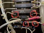
I’ll send picture of post I was checking and called them left and right because unsure of which one is 1or2

8CE57273-3D3D-4034-89DE-9B9212273818.jpeg
 

kloppk

Well-known member
Steel Soldiers Supporter
2,145
3,526
113
Location
Pepperell, Massachusetts
Based on those readings it would appear that R14 is defective.

Do a couple of other tests before we condemn R14.

With the set OFF and Dead Crank in OFF do the following.
1) Remove the wires from the AC Voltage Regulator terminals 1 & 3. Label if needed so they don't get mixed up.
2) Measure the resistance between those two wires. It ought to be about 25 to 35 ohms. What do you measure?

Make sure those two wires aren't touching anything.
3) Put the Dead Crank switch back to NORMAL
4) Start the set
Repeat the tests done previously and post the results.
Those tests were...
Hook you meters negative lead to the ground stud above the relays on the back wall.
With the set running check for the following voltages and reply what you measure for each test.
5) Measure the DC voltage at R14 terminal 1 with S1 held in the START position. You should read about 24 volts DC.
(R14 is located on the back wall of the control cube on the far left)
6) Measure the DC voltage at R14 terminal 2 with S1 held in the START position. You should read between ~5 and ~11 volts DC.
7) Measure the DC voltage at CR2 terminal 1 with S1 held in the START position. You should read between ~5 and ~11 volts DC.
(CR2 is located on the back wall of the control cube on the far le(.)
8.) Measure the DC voltage at CR2 terminal 2 with S1 held in the START position. You should read between ~5 and ~10 volts DC

Shut the set down and reconnect those two wires to the appropriate VR terminals.
 

Capt.Moondog

Member
Steel Soldiers Supporter
61
42
18
Location
Walnut Hill, Florida
With dead switch off and AC Reg wires 1&3 off they oms out at 32.
With wires 1&3 still off and machine running and S1 switch held to start..
R14- Leftpost 24v / Rightpost .2v
CR2- Leftpost 0v / Rightpost .2v
 
Top
AdBlock Detected

We get it, advertisements are annoying!

Sure, ad-blocking software does a great job at blocking ads, but it also blocks useful features of our website like our supporting vendors. Their ads help keep Steel Soldiers going. Please consider disabling your ad blockers for the site. Thanks!

I've Disabled AdBlock
No Thanks