• Steel Soldiers now has a few new forums, read more about it at: New Munitions Forums!

  • Microsoft MSN, Live, Hotmail, Outlook email users may not be receiving emails. We are working to resolve this issue. Please add support@steelsoldiers.com to your trusted contacts.

MEP-805B no power to fuel pump = won’t start

Dogger

New member
25
11
3
Location
Louisiana, USA
I’m in South Louisiana where recent hurricane wiped out our power. Read all manuals and associated forum threads. I’ve been tiresomely trying to figure out this MEP-805b genset but I’m missing something. Anyone way smarter than me feel free to call and advise. 337-580-3366 Thanks and may God Bless!
 

Guyfang

Moderator
Staff member
Moderator
16,763
24,068
113
Location
Burgkunstadt, Germany
Not receiving 24 volts to starter. I’m missing two varistors on the TB2-Load Output Terminal Board, not sure if they could/would be causing my problem or not.
No, the missing varistors have nothing to do with the starter.

Is the set new to you? Have you ever seen it run right? Did you follow the trouble shooting diagram? Will it turn over with the S10 dead crank switch?
 

Dogger

New member
25
11
3
Location
Louisiana, USA
No, the missing varistors have nothing to do with the starter.

Thanks for clearing my mind on the varistors! Is the set new to you? Have you ever seen it run right? Did you follow the trouble shooting diagram? Will it turn over with the S10 dead crank switch?
Yes, set is new to me. No I haven’t seen it run right. I did crank it momentarily by jumping 24 volts from batteries and engine fired right up. Been studying troubleshooting diagram for three days and now have nightmares about it, lol. Yes it will spin over with S10 and also with S1. MPU is a bit weak but adjusted to just over 2 volts (might be able to squeeze a little more but she’s almost bottomed out) trying to source another but feel like it’s not necessarily my culprit.
 

155mm

Chief and Indian
Steel Soldiers Supporter
1,178
389
83
Location
Guymon, OK
Any semi truck parts house has mpu that fits, tell them rtlo18918b transmission speed sensor in a kenworth not Peterbilt
 

Dogger

New member
25
11
3
Location
Louisiana, USA
Any semi truck parts house has mpu that fits, tell them rtlo18918b transmission speed sensor in a kenworth not Peterbilt
Thanks! I got parts house to order one, they should have it Wednesday. I appreciate your feedback. Just not 100% the MPU is my sole problem locking me out.
 

Dogger

New member
25
11
3
Location
Louisiana, USA
Looking at current MPU set up and it appears J13 red wire is attached to MPU white wire and J13 black wire is attached to MPU red wire. Can anyone verify if this is ok, do the wires even matter as long as both are terminated. This will also come into play when I receive and install the new MPU once it arrives.
 

155mm

Chief and Indian
Steel Soldiers Supporter
1,178
389
83
Location
Guymon, OK
It doesnt matter, the conputer is just looking for the number of on-off cycles per second.

The mpu is the reason these newer jenny’s are so much nicer. The computer controls the throttle, and when you set the hertz, the computer doesnt see 60 hertz, it sees 600,000 on off’s from the mpu, so when you add a load it drops to 550,000 on offs, and computer compensates
 

Dogger

New member
25
11
3
Location
Louisiana, USA
It doesnt matter, the conputer is just looking for the number of on-off cycles per second.

The mpu is the reason these newer jenny’s are so much nicer. The computer controls the throttle, and when you set the hertz, the computer doesnt see 60 hertz, it sees 600,000 on off’s from the mpu, so when you add a load it drops to 550,000 on offs, and computer compensates
Would you be able to tell me what R10 fault light is correlated with, it’s the only one I can’t get to clear.
 

Dogger

New member
25
11
3
Location
Louisiana, USA
Please post a picture of what you are calling R10. Are you getting any fault message on the CIM?
Key pad on CIM left and down arrows non-operational. Only msg is low oil pressure but clears when toggling reset. Not home to take picture but light is a red LED on circuit board.
 

Dogger

New member
25
11
3
Location
Louisiana, USA
8956AB0F-BF3D-4ADE-9337-7F63BEC487AC.jpeg
Here is a picture of where the fault light is that won’t clear, it’s R10 LED5. I managed to get the keypad working (hopefully my fix lasts for awhile) and the rest of fault lights to clear/reset. Also I changed the MPU and set it between 2.5-3v. When cranking I can barely see speed sensor light up. Still not getting power to fuel pump and therefore no start. Once running does fuel pump electric actuator receive a constant 24 volts? If yes, I’m tempted to just install a switch and a jumper from battery for supply.
I really appreciate everyone who has helped me along thus far!!! Still learning every day but sure would be nice to get this unit up and producing power for those without and in need.
 

mep805b

New member
4
10
3
Location
USA
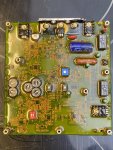
It appears you are not getting 24v to your injection pump. The error light you see is not related. The injection pump and fuel pump are two different animals. One is mechanical and the other requires voltage. I left a message with my phone number. Kindly pull the ESD5551 “Speed Control Unit " module (4 screws), remove the PCB and text a photo of the big blue capacitor. Here is a post of a similar fix https://www.steelsoldiers.com/threa...t-power-failure-solution.198527/#post-2314128 I have spares of these free of charge. They are free if you need them. I need to first confirm you are having the same exact issue that we had.
 

Dogger

New member
25
11
3
Location
Louisiana, USA
It appears you are not getting 24v to your injection pump. The error light you see is not related. The injection pump and fuel pump are two different animals. One is mechanical and the other requires voltage. I left a message with my phone number. Kindly pull the ESD5551 “Speed Control Unit " module (4 screws), remove the PCB and text a photo of the big blue capacitor. Here is a post of a similar fix https://www.steelsoldiers.com/threa...t-power-failure-solution.198527/#post-2314128 I have spares of these free of charge. They are free if you need them. I need to first confirm you are having the same exact issue that we had.
3247251E-D93E-4C9A-84F5-356EFBEE0389.jpeg167EE797-34D7-498A-96C0-0EEFEF141339.jpegC98F5A64-B7B5-4F58-AFA5-EFF9E1F1DFDF.jpeg
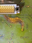
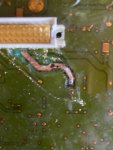
Had a electronics shop look at ESD5551 “Speed Control Unit " circuit board, they determined the capacitors were ok but copper trace on backside of board had a hot spot and separation. They soldered over the bad spot. I re-installed and the unit started right up. Now engine is running but generator is not producing power. I held the start to try and flash multiple times but was unsuccessful. Still have R10 LED5 fault but not sure if it's related to current issue. One step closer but still lots to learn in order to get where I need to be. Now to figure out where to focus next!
 

Chainbreaker

Well-known member
1,796
1,992
113
Location
Oregon
Anytime a circuit board trace gets hot enough to melt and cause an open there is a problem in that circuit...dead short or faulty component on that circuit or wiring harness issue, etc. They may have repaired the open circuit trace but fault has to be located to prevent a reoccurrence or additional issues in that circuit might occur.

Also, in the pictures you posted above it looks like the P24 connector has scorch marks on it near the capacitor. Wonder if that capacitor ever blew and was replaced earlier...?

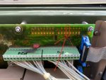
Another observation, in post #16 above photo, the mounting standoff just above P24 looks a bit funky on circuit board like it got hot around the mounting screw that attaches standoff to circuit board. If you notice the standoff on the right, it attaches to the green sheet metal behind it and there is no annular paint relief where it attaches, however on the left one that looks like it may have gotten hot, there is what appears to be an annular paint relief where its mounted to sheet metal making me think that is an "intentional grounding point" with perhaps a star washer on opposite side. Anyway, it looks like perhaps something might have shorted through it to that ground point. But hard to tell from photos and no hands on examination.
 
Last edited:
Top