• Steel Soldiers now has a few new forums, read more about it at: New Munitions Forums!

  • Microsoft MSN, Live, Hotmail, Outlook email users may not be receiving emails. We are working to resolve this issue. Please add support@steelsoldiers.com to your trusted contacts.

MEP-831A 120 Volt output Loading?

kloppk

Well-known member
Steel Soldiers Supporter
2,145
3,526
113
Location
Pepperell, Massachusetts
When the inverter voltage output switch is set to 120V what is the allowable current loading on L1 & L2 terminals?
I understand the max current at 120 volts is spec'd at 31 amps.
Can 31 amps be drawn from say L1-L0?
Or can L1-L0 only provide 15.5 amps max and L2-L0 only provide 15.5 amps max?

I search the TM and don't see any info on this aspect other than the 31 amps max current.

I suspect the inverter is actually a pair of 15.5 amp inverters that can be set to operate in phase for 120 volt operation or 180 out of phase for 240 volt operation depending on the voltage switch setting. Can anyone confirm this or explain what's really happening?
 

MarauderPPK

New member
4
0
1
Location
Deutschland
Inverter Current 15.5Amps only!

The Output connector description plate on the Gen Set tells you that.


I understood:

There are two inverters with 120VAC 15.5Amps inside, one connected to L1-N (L0) and the other connected to L2-N (L0) - everyone of them can provide 120VAC with 15.5Amps.
If you use them in serial mode, they both together provide 240VAC with 15.5Amps (like connecting batteries in a row; for e.g. two 12VDC Batteries in a row to provide 24VDC).
If you use them in parallel mode, each of them provide 120VAC with 15.5 Amps, one at Terminal L1 and the other at Terminal L2. They are both connected with the other leg to N (L0).


- in 240 VAC mode you can use full 15.5Amps with no load balancing between L1-L2... (my 831A is setup in this mode and provides 50Hz --> for Germany 230VAC 50Hz)
--> i think the two 120vac inverters are connected in a serial mode with one output L1-L2 - so the inverters working in a row.
.... Unfortunally, there are 120VAC between L1-N (L0) and 120VAC between L2-N (L0), too... if using this 120VAC, stay secured that 15.5Amps never exceeded per one phase!

- in 120 VAC only mode you must balance your load between L1-N (L0) and L2-N (L0) that every phase does'nt exceed 15,5Amps... ??
--> i think the two 120vac inverters are connected in parallel mode with seperated outputs L1-N (L0) and L2-N (L0). There are no 240VAC available.
.... i don't think you can connect both inverter outputs parallel - L1+L2 together and use them with N (L0) as 120VAC 31 Amps Output! I think this will kill the inverters.


Can you follow me?
 
Last edited:

kloppk

Well-known member
Steel Soldiers Supporter
2,145
3,526
113
Location
Pepperell, Massachusetts
Yes I follow.
But... The info posted by boatman69 contradicts your info regarding how much current can be drawn from L1-L0 in 120 volt mode. 15.5 amps vs 31 amps.
Hoping to find a definitive answer.

Guyfang - Do you agree with the 15.5 amp max per leg in 120 mode?

If indeed it's 15.5 amps per leg in 120 v mode what purpose does flipping the 120/240 mode switch do other than setting the inverters to be in phase vs 180 out of phase? Either way both inverters are still outputting their 120 to the two legs and are limited to 15.5 amps so flipping the switch buys you nothing for power output other than having both 120 legs in phase?
 
Last edited:

MarauderPPK

New member
4
0
1
Location
Deutschland
120V AC and 15.5Amps per Inverter!

I found some information cards (laminated A4) inside the top of the gen set. The first two posts of kloppk and boatman69 are right.
My previous post was a little bit wrong so i have to correct some information that i given:


In 240V AC Mode the Voltmeter M1 is connected to the Terminals L1 - L2 and shows the full Voltage of the two inverters working in a row (serial mode).
If you use 120V AC connecting your loads between L1 - N (L0) and L2 - N (L0), you have to balance your loads (3-wire system).
Remember: Every inverter can only provide 15.5Amps - so don't exceed the limits!


In 120V AC only mode, the voltmeter M1 is connected to the Terminals L1 - N. The Terminals L1-L2 are shortcut by the switch (parallel mode).
Both inverters may work now in parallel mode. There's no 240V AC available, but there are 120V AC with 31 Amps available.
So use 120V AC connecting your loads between L1 - N (L0) or L2 - N (L0), you don't have to balance your loads (2-wire system).
Remember: Every inverter can only provide 15.5Amps - both together provide 31 Amps. Please don't exceed the limits!


Well, let's check this informations in the schematics of the gen set: (sorry for the bad quality - the boardsystem here resized the picture!)

MEP-831A Gen./Inv. schematic - Schematic of the MEP-831A   showing: Generator Inverter Terminals


MEP-831A  AC schematic - shows:  120V / 240V - AC -Switch

For electrical security reasons, please don't forget to connect a ground wire to the ground terminal.
If we told about 3-wire and 2-wire system, only the power wires are counted! You need an additional wire for ground.
Never use your loads without a grounding wire (a third wire) connected to the ground wire on the gen set.
 
Last edited:

calsdad

New member
22
2
3
Location
Chelmsford MA
I ran across this thread while I was boning up on my knowledge of the MEP-831a after getting two of them. I've got one of them fully up and running - and was still curious as to how much the unit would really put out.

So I ran an experiment this afternoon. First I had to stop by HD and pick up an ammetter - then I got the 831 hooked up to my workshop and got a bunch of stuff running against it after hooking it up to the 120V drop I have going to the shop.

I got it up to 25 amps steady draw by running the following:

Three 4 bulb 48" hanging flourescent lights
The dust collector for my sandblast cabinet which has a motor rated at 6 amps
A Delta disc sander supposedly rated at 1/2hp ( I can't find the amp rating)
A Munters diesel heater that's rated 7 amps to drive the fan and electrics

The 831 seemed to drive all of this just fine.

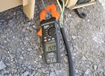
I put the ammeter on it with all this stuff running - and it was showing around 19 amps steady.

MEP-831a_3-18-2018_ 19amps.jpg

Then I hooked up a Porter-Cable 7 inch framing saw - and tried powering that up while the rest of the load was running.

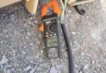
What I saw was some spikes on the ammeter up as high as 48 amps momentarily. Usually it would spike up to 42-45 amps or so before
settling down to just over 30 amps on the ammeter or 3Kw on the 831's meter:

MEP-831a_3-18-2018_ 3Kw-output.jpgMEP-831a_3-18-2018_42.24-amps.jpg

Looks to me like the unit will easily put out it's full amp rating while outputting 120v
 
Top
AdBlock Detected

We get it, advertisements are annoying!

Sure, ad-blocking software does a great job at blocking ads, but it also blocks useful features of our website like our supporting vendors. Their ads help keep Steel Soldiers going. Please consider disabling your ad blockers for the site. Thanks!

I've Disabled AdBlock
No Thanks