loosegravel
Just a retired mechanic who's having fun!
- 504
- 893
- 93
- Location
- Enumclaw, Washington
Steel Soldiers now has a few new forums, read more about it at: New Munitions Forums!

I know! I tried to Google that kit number, but nothing comes up. I actually ordered a new connecting rod and the “valve cap” from someone else because I didn’t know that they’d be in this kit. I’ll just return them.Wow, what a deal! Essentially you paid for the injector and got 30 additional OEM parts for free! Can't beat that price!
 Ok, the engine is back inside of this unit. I have it running and just going through the governor system set procedures. I have checked the linkage spherical nut and it’s showing one thread at the bottom. Step 2 of the actuator GAC is confusing to me. “Make sure the actuator lever reaches the end of it’s stop just prior to the engine fuel lever reaches its stop.” It doesn’t say what the position of the manual start knob should be. It definitely makes a difference.
The PMA is the Permanent Magnet Alternator (AKA the thing attached to the engine). You want to measure voltage between terminals A&B on the controller. The hand knob is setting the RPM "floor", so you want to move it towards 'start' to raise the no-load RPM, or toward 'stop' to lower RPM. The upper screw with locknut sets the highest you can lock the hand knob at, farther in = lower manx RPM floor.Step 1 of the speed/load controller GAC says to adjust the speed pot on the governor control to obtain a PMA voltage of approximately 178 +/- 2vac. I’m not sure what PMA is or where to measure it.
Very cool. Thanks for the help. Now that I know where to measure the PMA voltage I should be able to proceed here. I still don’t know if Im supposed to set the no load on the manual start knob fist though. I’ll try that. Thanks again!The PMA is the Permanent Magnet Alternator (AKA the thing attached to the engine). You want to measure voltage between terminals A&B on the controller. The hand knob is setting the RPM "floor", so you want to move it towards 'start' to raise the no-load RPM, or toward 'stop' to lower RPM. The upper screw with locknut sets the highest you can lock the hand knob at, farther in = lower manx RPM floor.
I haven't had the joy of trying to make one of the GAC controllers work, but I can say I'm very happy mine had one of Kurt's controllers in it already. Just set that and the magnet gap, and with his you're good to go...
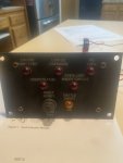
Thanks Kurt!The two circled terminals are where you measure the PMA voltage.
View attachment 890903

Excellent! Thanks my friend!Wiring diagrams are at the veerrrrrrry end of the TM... which I learned while trying to thumb through it on my phone one evening in the cold.
Ok, thanks Kurt. I’m going to see if I can find the schematics it the back of the TM like fb4 said. I’m sure that it’s a simple problem.Correct. The HT switch in the back of the block is a NO switch.

