• Steel Soldiers now has a few new forums, read more about it at: New Munitions Forums!

  • Microsoft MSN, Live, Hotmail, Outlook email users may not be receiving emails. We are working to resolve this issue. Please add support@steelsoldiers.com to your trusted contacts.

MEP 831a Fault test not working and strange connector

synelecpb

New member
15
7
3
Location
point pleasant NJ
Hi All,

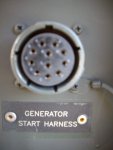
I've been lurking around this community and finally have purchased my own 2011 MEP 831a! I'm having an issue though that I feel like i've seen others have, but can't seem to find anywhere in the threads. Everything works as it should except the fault test button won't light the lights, and there is a plug wired into the control box. I feel like these issues are somehow related, like perhaps this unit was meant to be a slaved unit? Or remotely operated? Any assistance would be most appreciated.

Thanks!
 

Attachments

kloppk

Well-known member
Steel Soldiers Supporter
2,145
3,526
113
Location
Pepperell, Massachusetts
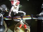
Very odd. I suspect it's a remote start connector judging by the way it's routed to the switch's on the control panel and the round hole on the left cabinet wall.
 

kloppk

Well-known member
Steel Soldiers Supporter
2,145
3,526
113
Location
Pepperell, Massachusetts
Wow, You have Kurt nearly stumped on that one.;-) Hmmmm?
:lol:

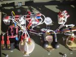
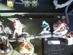
Because of 69birdman's zinger ;-) I took a close look at the picture to see where the wires got to from the mystery plug.
Yes - it's a Remote Start cable. It allow the generator to be Pre-Heated, Remote Started, the contactor to be closed and I *think* remotely see the AC voltage.

From what I can see it looks like...
Yellow wire goes to S18-1 to control Pre-Heat
Green Wire goes to Ground

Red Wire goes to S1-2
Pink-ish wire goes to S1-3
Purple-ish wire goes to S1-S1-4
Gray wire goes to S1-1
These would be for remote starting

Brown wire goes to S5-2 to control the contactor.

I can't tell where the Blue & White wires go but I suspect they go to the AC volemeter to remotely monitor the AC voltage.

It would look like having this harness installed but not hooked up to anything would not interfere with the generator working normally from it's front panel controls.

The wires in the mystery harness have shrink tube labels on them and the black wire loom so it tells me it's a proper harness and not some hack job.

Again, all this is based on what I could kind of make out in the picture.
 
Last edited:

synelecpb

New member
15
7
3
Location
point pleasant NJ
Ah, thanks so much! I’m guessing i should just leave it alone in there and not try to remove it. It seems to have been loomed in by someone who knew what they were doing, so it’s not like a bunch of loose wires flapping.
That leaves me with the curious case of the fault indicators not working. The way it was told to me by the seller, that issue had something to do with that connector (he thought) or that because whatever that connector was supposed to connect to wasn’t connected - the fault test wouldn’t work. If any ideas come to mind please let me know. The Concorde battery seems completely shot, 2.5v no matter how much i hit it with a CC power supply. New battery retrofit is my next step.
 

kloppk

Well-known member
Steel Soldiers Supporter
2,145
3,526
113
Location
Pepperell, Massachusetts
If the Concord is stuck at 2.5 v it's very likely it's badly sulphated and beyond hope.
A pair of 12v motorcycle batteries work well. I have them in both of my 831's.

I'll spend some time tomorrow and try and give you a couple of things to measure to troubleshoot the fault monitor.
 
Last edited:

Guyfang

Moderator
Staff member
Moderator
16,768
24,094
113
Location
Burgkunstadt, Germany
Kurt,

How about simply shorting across the oil pressure switch, to see if you get a fault light? Let's see if the fault indicator even works. I have replaced several during the time I worked on them. Or any othe safety switch? See if you get an idiot light, then see if you can reset it?

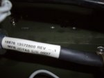
Are there any markings, tags or such things on your mystery harnes? Does it look like a milatary installation? If so, I might be able to ask someone what it might all do.
 

synelecpb

New member
15
7
3
Location
point pleasant NJ
I have a few of the foremost experts on these generators engaged, thanks guys!
The harness has no markings, but I'll look again. I'm pretty sure it's a military installation. I pressed the seller for more info - He said its an air force unit, 2011 manufacture (which can be seen on the data plate) that he was told was specifically ordered the way it is for something they were going to do and then never used for that purpose. He got it with 2 hours, now has 72 hours. Are there more photos or angles that would be helpful? Please let me know and I'll post them. Thanks again.
 

kloppk

Well-known member
Steel Soldiers Supporter
2,145
3,526
113
Location
Pepperell, Massachusetts
Guy,
I think the problem is either no power to the monitor or it's shot. The OP indicated the Fault Reset button won't illuminate any of the LED's.
Looking at my schematic of the Fault Monitor if the Reset button won't illuminate all the LED's then there is a basic problem.

synelecpb
Two things I'd recommend checking.
1) Disconnect P4 from the Fault Monitor. Check that none of the metal terminals in the P4 housing have been pushed back out of position.
Reconnect P4 and look at the terminals thru the back of P4 to be sure none have pushed back when it's plugged in.

2) Then I'd recommend checking for power and ground to the Fault Monitor assembly at it's P4/J4 connector.
With S1 in the RUN position use a DC voltmeter and probe the back of the P4 connector across pins 6 & 7. Negative meter probe to pin 6 and the positive probe to pin 7.
The pin numbers are molded into the plastic housing of the fault monitor.
You can insert the meter probes inside the back of P4's white plastic housing to make contact with the contacts in the connector housing.
See if you measure ~24 volts DC.
If so then press and hold the fault monitors Fault Reset button an verify ~24 volts DC remains across pins 6 & 7.
If the 24 volts DC remains on 6 & 7 then look to see if all the LED's illuminate on the panel.
If you get the ~24 volts DC during those steps and the LED's won't illuminate then the Fault Monitor assembly has an issue.

If you find the Fault Monitor is shot I can send you a copy of it's schematic for you to use to troubleshoot and repair it or if you want you can send it to me and I'll repair it for you.
 

Guyfang

Moderator
Staff member
Moderator
16,768
24,094
113
Location
Burgkunstadt, Germany
I have a few of the foremost experts on these generators engaged, thanks guys!
The harness has no markings, but I'll look again. I'm pretty sure it's a military installation. I pressed the seller for more info - He said its an air force unit, 2011 manufacture (which can be seen on the data plate) that he was told was specifically ordered the way it is for something they were going to do and then never used for that purpose. He got it with 2 hours, now has 72 hours. Are there more photos or angles that would be helpful? Please let me know and I'll post them. Thanks again.
Pictures are always good. I like to keep such things in a file for each set. I am sure Kurt would also.
 

kloppk

Well-known member
Steel Soldiers Supporter
2,145
3,526
113
Location
Pepperell, Massachusetts
Pictures are always good. I like to keep such things in a file for each set. I am sure Kurt would also.
You're most right Guy!

Close up pictures of each switch and gauge that the wires go to would be great.
A closeup up of part number on the strange connector.
Also a close up picture of the pin side of the connector like in your original post but much closer. Hopefully the pin location markings are visible.
Lastly if you could remove the back shell cover off the connector and take some pictures to show where the various colored wires go would be very helpful.
 

smokem joe

Active member
499
68
28
Location
Green OH
Sounds almost like the Tobyhanna mod on the 802/803 series for remote start. Any way the fault lights are exported out that harness as well so not active on the panel?
 

kloppk

Well-known member
Steel Soldiers Supporter
2,145
3,526
113
Location
Pepperell, Massachusetts
It doesn't appear to be the case based on what wire connections I could spot in the pic.
I'm hoping the OP does the tests I suggested so we can get to the bottom of the LEDs not lighting when the button is pushed.
 

robson1015

Active member
515
132
43
Location
New Concord, Ohio
Hi All,

I've been lurking around this community and finally have purchased my own 2011 MEP 831a! I'm having an issue though that I feel like i've seen others have, but can't seem to find anywhere in the threads. Everything works as it should except the fault test button won't light the lights, and there is a plug wired into the control box. I feel like these issues are somehow related, like perhaps this unit was meant to be a slaved unit? Or remotely operated? Any assistance would be most appreciated.

Thanks!
Hi -had the same issue a few years back. Look at the sticky on top of the page for the mep-831 -page 7. I disconnected the wiring harness for the remote start plug and used the wiring diagram to re attach the wires...
 

robson1015

Active member
515
132
43
Location
New Concord, Ohio
Look at page 8 in the sticky. I actually didnt disconnect the harness, I found the two missing wires wrapped under the blue wire and connected them to the proper terminals.
 

synelecpb

New member
15
7
3
Location
point pleasant NJ
Wires

Robson1015, you're a lifesaver! I read through the sticky completely a long time ago, and vaguely remembered that post. That and the 'strange solar charger wiring' posts from others. I just didn't make the mental connection from my issue to yours. LOL.
Now I have to figure out where they go.
Thanks!
 

Attachments

Guyfang

Moderator
Staff member
Moderator
16,768
24,094
113
Location
Burgkunstadt, Germany
I have to admit, I would simply remove the wires and harnes. This kind of setup is in the norm, applied in parallel to the existing circuits. Simply removing it should not effect the operation of the gen set.
 

robson1015

Active member
515
132
43
Location
New Concord, Ohio
Robson1015, you're a lifesaver! I read through the sticky completely a long time ago, and vaguely remembered that post. That and the 'strange solar charger wiring' posts from others. I just didn't make the mental connection from my issue to yours. LOL.
Now I have to figure out where they go.
Thanks!
You are very welcome, It's nice to be helpful on here after all the help I've received ....
 
Top
AdBlock Detected

We get it, advertisements are annoying!

Sure, ad-blocking software does a great job at blocking ads, but it also blocks useful features of our website like our supporting vendors. Their ads help keep Steel Soldiers going. Please consider disabling your ad blockers for the site. Thanks!

I've Disabled AdBlock
No Thanks