• Steel Soldiers now has a few new forums, read more about it at: New Munitions Forums!

  • Microsoft MSN, Live, Hotmail, Outlook email users may not be receiving emails. We are working to resolve this issue. Please add support@steelsoldiers.com to your trusted contacts.

MEP-831A Freq Converter (A8) rebuild - anybody have luck with repairing these?

Demoh

Member
217
26
18
Location
St Pete, FL
So ive been going through an 831 in the spare time while I wait for parts to come in for my 803s, and aside from the unit being close to mint with a 12 hour engine, This unit has an overvolt condition. L1 - L2 is over 400 volts, L1 - N is 200+ and L2 - N is the remainder.

Alternator on all 4 phases/poles and all 3 windings on each phase test good including the charging coil. Roughly 200vac on my backup "I cant find my meter, I guess this will do" harbor freight meter, 15 ohms per coil for the HV side. Potentiometer sweep seems within spec, its a 0-5k pot right? Im not quite getting 5k out of it but I blame the meter.

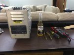
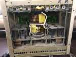
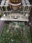
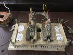
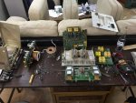
Ive done all of the pertinent tests in the TM so I ended up pulling A8 out of the unit and fully disassembling it. Looks like the depot threw in a unit pulled from the sand dunes overseas and then ran it until it got submerged in water. I cant find any traces of magical smoke being let out anywhere so I think if I just give this unit some TLC, test the components I can test, and reassemble I should be good.

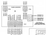
Does anybody have experience rebuilding these units? These look super simple except the logic board and whatever issue I have with an overvolt is going to be either a bridged HV trace, the sense circuit so the logic doesnt know how high it is, or the actual drivers doing the work. Either way this shouldnt be much different than the CNC spindle driver that I rebuilt in my milling center. (That unit has a firmware and a lot more complexity to it though)

I will say I am very impressed in the robustness of this module. Definitely feels overengineered compared to my mill stuff and the 20-50 kva 3 phase battery backups that I worked on in the past. (The UPS the size of a half height server rack cabinet that Ive worked on the internals seems more like cracker jack box components compared to this thing.)

Of course it wouldnt be any fun without pictures. Also I tasted the dust, it tastes just like the dust in my 803 that came from Kuwait. Does anybody know if all of the dust over there tastes the same? :mrgreen::mrgreen:

image1.jpgimage2.jpgimage3.jpgimage4.jpgimage5.jpg
 

Demoh

Member
217
26
18
Location
St Pete, FL
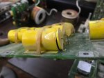
So now that I have 80% of this thing mapped out, I ended up finding where some smoke escaped...

image6.jpg

So the DC side 400volts. The neutral is center tapped on the filter caps that the inverter gets its juice from. The AC cap that let the smoke out is rated for 160VAC or 250VDC. The question now becomes was the AC cap that blew up was that cause or effect? I am thinking effect.

My theory is the main inverter (the 100 amp solid state switch basically) was told to go full tilt effectively putting some excessively high voltages through the AC caps. This leads me to think that either A) the downstream voltage sense is jacked up so it thinks its lower than it is or B) the inverter control is jacked and giving it higher than it wants. Im leaning more towards option A because the inverter should throttle down if it thinks it is out of range. This would also mean anything DC side and before that is good.

Lets keep in mind when it comes to electronics I fully understand only about 80% of this circuit and have created a schematic for it in about an hour. The controls I know nothing about as my electronics knowledge doesnt go that far.

Does anybody have any suggestions on what would be a good solvent to remove all of this caked on dust but also doesnt take the potting off of the boards? I can deox the connectors and stuff but I need to know what to dip my toothbrush in as water or alcohol just dont cut it for this application.
 

DieselAddict

Well-known member
Steel Soldiers Supporter
2,541
2,090
113
Location
Efland, NC
For general board cleaning I use DI water and/or IPA. Back before the EPA got involved in this stuff we used R11 refrigerant to clean boards. Worked great but was horrible for the environment.

Removing that coating will require a compatible solvent. One I would suggest trying acetone. Cross your fingers and hope its acrylic. I expect it won't be that easy though. I don't know what coating they are using but if I were to guess my money is on urethane. That will take more than acetone to soften it if I'm right. I'm planning to take one of my spares apart to check it out. I've seen where the coating begins to degrade and allows moisture to stop the inverter from working.

I'm interested to see what you've scoped out for the schematic. I've been planning to do the same thing since I can't find any real info online about it. This inverter should be more like a VFD than a normal DC/AC inverter. These will have an input rectifier to charge a high voltage DC bus. Looking at the transformer it appeared that the DC side was pretty high voltage and relatively low current in comparison with normal 24-48v DC inverters.

Keep us posted on how it goes. Let me know how I can help.
 

Demoh

Member
217
26
18
Location
St Pete, FL
India Pale Ale? My brother would approve of this method but I dont think I would. Yea water and ipa is normally not solventy enough to break through the crud. plus any time i use alcohol it leaves horrible residue... looking to find a product that works...

I do not want to remove the coating. I have my own methods for that. I want a tough solvent that is compatible with the coating so it does not damage it. Im thinking maybe starting fluid or some other light hydrocarbon.

As for a schematic I drew one up on the side of a shoebox with a permanent marker. It only covers the basic theory of the unit to aid me in troubleshooting and it wasnt too bad because the traces are huge and its only a 2 layer board. No traces that you cant see in the center. :-D As for how it gets the inverter to run, it uses a 100dy-24nf per phase right off the DC before going to the cores and AC caps.

Does anybody have component sources for these AC caps? arcotronics mkp c.4g series, 20uf 250vdc 160vac... mouser ill have to call for a quote, found some used pulls in the flea bag from china, but nothing else really. I see there are some alternatives but going through the component specs they dont quite line up so I would rather not substitute.

I might show up at Technology Research Corporation which makes the bulk of the mep series electronics because they are down the street from me in Clearwater, maybe try to make some friends with an engineer there or something. They probably have some privileged info because from looking at the boards this unit was meant to be worked on and repaired. Wishful thinking, I probably wouldnt get past the front door.

DieselAddict, do you have any bad units? The gears in my head are starting to turn. I only have 1 831 and only tinker on it when waiting on parts for my 803s, but I have all my equipment from when I repaired 6.0 FICMs and TVs..... I didnt really want to get into electronics repair again but after actually messing with the 831s I can see a need for it now. (like I need more stuff to do... :roll::roll:)
 

Demoh

Member
217
26
18
Location
St Pete, FL
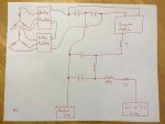
Here is the crude non-shoebox version of what I have so far. This doesnt include any controls, etc.... T is the big honkin inductor in the pictures, the inductor between the 2 AC caps are the smaller inductors mounted next to one of the big guys, and the inductor labeled RFI is labeled that because thats what it is labeled on the PCB.

Theres also some other components involved, a relay etc...

This schematic is to be doubled, 1 for L1 and 1 for L2, sharing the neutral (I assume), and although I havent traced it yet, I have a hunch the relay just bonds the L1 and L2 together and changes the timing so both inverters arent opposing each other.

image7.jpg
 

kloppk

Well-known member
Steel Soldiers Supporter
2,168
3,607
113
Location
Pepperell, Massachusetts
... I have a hunch the relay just bonds the L1 and L2 together...
Would like to hear if you can confirm this is true for 120V operation.
Some have stated that in 120 V mode you can pull all 3 KW from say L1-N, others have said no, you can only pull 1.5 KW from L1-N, and 1.5 KW from L2-N in 120 V mode.
 

Demoh

Member
217
26
18
Location
St Pete, FL
Would like to hear if you can confirm this is true for 120V operation.
Some have stated that in 120 V mode you can pull all 3 KW from say L1-N, others have said no, you can only pull 1.5 KW from L1-N, and 1.5 KW from L2-N in 120 V mode.
With the equipment I have I can confirm or deny this. My test methodology should be something along the lines of hook scope up to L1 and L2 referenced around N in 120/240 operation and see what she looks like. This will be my baseline. Then I will hook up somewhere upstream in the circuit before said relay (or board alltogether) and test again, should get same readings minus what that last ferrite does, ill probably end up hooking up right between the RFI and middle ferrite as there are screw lugs there. Then shut down, switch over, fire up then probe around to see what changed. Theoretically if my suspicion is correct Ill see 2 overlapping waves which would mean 3kw instead of 1.5.

Another test would be to amp meter the 2 6 wire connections because each 6 wire connection controls 1 side of the 2 sided inverter. put a load on L1 and watch one set of 6 go up in amperage, confirm that the other does not. Repeat for L2. Then repeat in 120v mode. THIS IS ASSUMING the DC side isnt bonded together. if the DC is bonded together then regardless of what leg you pull from its would pull from all alternator windings equally.

Upon further thought, I could probe right on the inverter modules way upstream after the DC as a test point, maybe even throw a CT on the big ferrite as I have those laying around.

So many ways to skin a cat....
 

ECS

Member
87
50
18
Location
Florida
Could someone please tell me where can I buy a replacement frequency converter the mep-831a?


fixed typo
 
Last edited:

DieselIron

Member
20
34
13
Location
Nashville, TN
I guess I just have to ask... were you successful in getting your inverter going again?
Has anyone else been able to restore these inverters when they fail?
 

ECS

Member
87
50
18
Location
Florida
I guess I just have to ask... were you successful in getting your inverter going again?
Has anyone else been able to restore these inverters when they fail?

Yes I got it going again after drying it out with a hair dryer, like was suggested.

If it rains and if very humid it would not start and run from cold and was getting that error.
Once it is running even if raining and extremely humid it performs good and did not get the error until it cooled down and was not running in the high humidity.
 

Aby3250

New member
13
2
3
Location
Puerto Rico

DieselAddict

Well-known member
Steel Soldiers Supporter
2,541
2,090
113
Location
Efland, NC
I hate to be the bearer of bad news but we don't have any technical info on the inverter itself. That is something a number of us here on the forum have wanted to find in an effort to facilitate repairs to the inverters but that has been an unfulfilled desire.
 

kloppk

Well-known member
Steel Soldiers Supporter
2,168
3,607
113
Location
Pepperell, Massachusetts
I will appreciate your help. I bought a Mep831a and a faulty capacitor in the inverter was repaired. When I connect it and turn on the generator, it generates current for 2 seconds and then it gives me an overload error. What could it be? Thank you! If you have a diagram of the inside of the inverter, I would appreciate your help.
It seems the main control board is the culprit when that happens. Many people experience that same fault if they are in a high humidity environment. It's related moisture genning into the numerous un-sealed potentiometers on main control board on the engine side of the inverter. Some have had success by running the engine with the inverter unplugged and allowing the engines heat bake out the moisture. Then shut the engine down, reconnect the inverter and start it up again.
To try and prevent it from happening again some have had success in removing the main control board, baking it at a low temperature in an oven to get the moisture out and then seal all the pots with conformal coating. There are also some exposed traces and other areas that should be sealed up too on that board.
 
Top
AdBlock Detected

We get it, advertisements are annoying!

Sure, ad-blocking software does a great job at blocking ads, but it also blocks useful features of our website like our supporting vendors. Their ads help keep Steel Soldiers going. Please consider disabling your ad blockers for the site. Thanks!

I've Disabled AdBlock
No Thanks