• Steel Soldiers now has a few new forums, read more about it at: New Munitions Forums!

  • Microsoft MSN, Live, Hotmail, Outlook email users may not be receiving emails. We are working to resolve this issue. Please add support@steelsoldiers.com to your trusted contacts.

MEP 831A Issues with not charging the lugs

bcheval

Member
41
11
8
Location
Ft Worth Texas
I am having a problem with my MEP-831A. The engine is running well. However, it will only charge the lugs in when I activate (Battle Short) and then close the interrupter. If I start the unit and try to set the interrupter without the Battle short on, the lugs will not charge. Yes, I have the manual and have followed the instructions up to consult the unit level.
Any ideas?
 

kloppk

Well-known member
Steel Soldiers Supporter
2,166
3,592
113
Location
Pepperell, Massachusetts
Has the contactor worked correctly in the past for you?

The engine RPM won't change until there is a load applied.
Without a load it's supposed to run at 3,050 RPM.
At full load the RPM would be 3,450 RPM.

I'd suggest making the following DC voltage measurements to narrow down the problem.
1) Connect your handheld meters negative lead to chassis ground.
2) With Battle Short OFF start the generator.
3) Verify that inside the three relays that only the rightmost one has its internal LED illuminated. Is it?

While holding the Contactor switch UP measure the DC voltage at the following points in the following order.
a) S5-5
b) S7-8
c) S7-9
d) K15-8
e) K15-12
f) K12-4
g) K12-12

Post the DC voltages at each of them. They will be either about 0 volts or about 24 volts.
Also answer to question 3.

Here are the terminal layout for the relay sockets. Same layout for K12.
Relay Terminals.jpg
-
 

bcheval

Member
41
11
8
Location
Ft Worth Texas
Has the contactor worked correctly in the past for you?

The engine RPM won't change until there is a load applied.
Without a load it's supposed to run at 3,050 RPM.
At full load the RPM would be 3,450 RPM.

I'd suggest making the following DC voltage measurements to narrow down the problem.
1) Connect your handheld meters negative lead to chassis ground.
2) With Battle Short OFF start the generator.
3) Verify that inside the three relays that only the rightmost one has its internal LED illuminated. Is it?

While holding the Contactor switch UP measure the DC voltage at the following points in the following order.
a) S5-5
b) S7-8
c) S7-9
d) K15-8
e) K15-12
f) K12-4
g) K12-12

Post the DC voltages at each of them. They will be either about 0 volts or about 24 volts.
Also answer to question 3.

Here are the terminal layout for the relay sockets. Same layout for K12.
View attachment 883912
-
Here is what I've got.
K15 LED is on
Voltages as follows, in DC. Contactor held in the closed position

a) S5-5 (28V)
b) S7-8 (28V)
c) S7-9 (0V)
d) K15-8 (0V)
e) K15-12 (3V)
f) K12-4 (0V)
g) K12-12 (29V)

Thank you for the help, do you think it's a bad relay or inverter?
 

kloppk

Well-known member
Steel Soldiers Supporter
2,166
3,592
113
Location
Pepperell, Massachusetts
Based on those readings it would look like the problem is inside the Inverter.
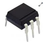
Specifically, there is a Solid-State Relay (SSR) K8 inside the Inverter isn't "closing" to enable the contactor to close and send power to the lugs.
The problem could be with K8 or the circuitry in the inverter that tells K8 to "open" and "close".
The K8 part number is: AQV251
The part is available from Mouser Electronics should you like to try and replace it.
AQV251
SSR AQV251.jpg

Your last reading is an error. K12-12 is tied to ground.

The SSR's on the "main board". The K numbers on the board do NOT match the K numbers in the TM.
I could figure which one is K8 on a dead board here if you choose to try and replace it.
SSR's on Inverter Board for TM K3 K6 K8.JPG
 

bcheval

Member
41
11
8
Location
Ft Worth Texas
Based on those readings it would look like the problem is inside the Inverter.
Specifically, there is a Solid-State Relay (SSR) K8 inside the Inverter isn't "closing" to enable the contactor to close and send power to the lugs.
The problem could be with K8 or the circuitry in the inverter that tells K8 to "open" and "close".
The K8 part number is: AQV251
The part is available from Mouser Electronics should you like to try and replace it.
AQV251
View attachment 884556

Your last reading is an error. K12-12 is tied to ground.

The SSR's on the "main board". The K numbers on the board do NOT match the K numbers in the TM.
I could figure which one is K8 on a dead board here if you choose to try and replace it.
View attachment 884557
Is it possible to buy a new board or send mine out to be repaired?

OR just buy a new inverter?
 

kloppk

Well-known member
Steel Soldiers Supporter
2,166
3,592
113
Location
Pepperell, Massachusetts
Something you should check is the AC voltage across terminals A & B on the Governor Controller behind the gauge panel.
Do this with the engine running and no load applied.
At no load the AC voltage should be about 178 volts AC. If your meter can measure frequency the AC frequency across those terminals should be about 254 Hz.
 

bcheval

Member
41
11
8
Location
Ft Worth Texas
Sounds like a bad inverter.
Like I said we never repaired the inverters just replaced.
I have no internal parts for it, I do have a brand new in the box inverter and I also have a 50 hz inverter that I cranked the freq. pot up to 60 hz.
Dewie,
Are you interested in selling them?
 

bcheval

Member
41
11
8
Location
Ft Worth Texas
Something you should check is the AC voltage across terminals A & B on the Governor Controller behind the gauge panel.
Do this with the engine running and no load applied.
At no load the AC voltage should be about 178 volts AC. If your meter can measure frequency the AC frequency across those terminals should be about 254 Hz.

Here is what I have.
AC Voltage @ A, B & C = 125V Each
293Hz Each
 
Top