• Steel Soldiers now has a few new forums, read more about it at: New Munitions Forums!

  • Microsoft MSN, Live, Hotmail, Outlook email users may not be receiving emails. We are working to resolve this issue. Please add support@steelsoldiers.com to your trusted contacts.

MEP002A - holding at 140 volts?

445gsdss

Member
29
0
6
Location
Winchester, VA
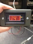
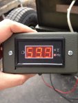
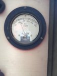
I have a new to me MEP002A that I recently purchased 2nd hand from the orginial GL purchaser. I've been scouring this forum and making a lot of posts since. Yesterday I fired it up and it started and ran fine - however I noticed an issue. When the engine RPM was set so hertz (on a little external meter/pannel the PO provided) showed ~60, the voltage meter show 140 volts. Also, while the digital meter showed stabile hertz, the analog meter on the generator was bouncing all over most of the time. The digital meter showed 140 volts also. Is this a sign of an issue or problem?

edit - forgot to mention, the voltage knob was turned all of the way to the left. (All of the way down).

Thanks,

445GSD

Photo Nov 23, 14 24 51.jpgPhoto Nov 23, 14 25 31.jpgPhoto Nov 23, 14 25 45.jpg
 
Last edited:

Rapracing

Member
271
0
16
Location
Western Pennsylvania
Maybe a stupid question but did you try adjusting the voltage with the knob under and to the left a bit of the the voltage gauge? The throttle (Hz) adjustment does not adjust voltage only the hz
 

doghead

4 Star General /Moderator
Staff member
Super Moderator
Steel Soldiers Supporter
26,246
1,182
113
Location
NY
Did you try to adjust the voltage with the voltage adjust knob on the control panel?

Have you read the operating instructions in the TM?
 

Suprman

Well-known member
Supporting Vendor
6,862
700
113
Location
Stratford/Connecticut
They like to see a load. Plug a heater into the aux outlet give it at least a little load let it really warm up and then see if you can adjust the idle, voltage and freq.
 

Isaac-1

Well-known member
1,970
50
48
Location
SW, Louisiana
Ok, this may seem like a strange question, but did the volts go up if you turned the knob to the right? If so you may just need to adjust the voltage pot on the AVR circuit board, there are 2 adjustable pots on it one is voltage similar to the front panel knob in function the other is stability, someone here should be able to tell you which one is which (I don't recall off hand) or it is in the TM.

Ike
 

jamawieb

Well-known member
1,436
557
113
Location
Ripley/TN
First make sure you have everything set to 120 or 120/240 1 phase and make sure your phase selector switch (under the cover, right above the convenience outlets) is set to 1 phase 120/240.
I've got similar problems with a unit I just got from GL. Your high voltage is either the voltage regulator or T2 transformer (usually this is what I always find). To test to see if it is the voltage regulator, all you have to do is take lead 17 off the voltage regulator board (when the unit is off), then start the unit and if the voltage increases the voltage regulator is working correctly. Then you can take the leads off the T2 transformer in the cubicle and test with an ohm meter, below is the TM's on the correct ohms for the transformer.
After you get the voltage correct try putting a load on the unit, sometimes that will stop the frequency meter from jumping around.
HIGH GENERATOR OUTPUT VOLTAGE (NO LOAD).
Step 1. Check for voltage regulator failure. Remove voltage regulator lead (wire 39C16) from terminal 17.
If voltage goes even higher, the voltage regulator is good.
Test and repair defective regulator (paragraph 6-6),
Step 2. Check voltage adjust rheostat (R1).
Replace rheostat (R1) if necessary.
Step 3. Check current voltage transformer (CUTI) (paragraph 6-9b(7)).
Replace bad transformer.
Step 4. Check transformer T2 (paragraph 4-38( 15), TM 5-6115-584-12).
Replace bad transformer.


Transformer (T2) (see figure 4-33). Tag
and disconnect four leads to transformer T2. Check
primary winding by measuring resistance from terminal
H1 to H2. Resistance should be 155 ohms
± 15.5 ohms. Check secondary winding by measuring
resistance from terminal X1 to X2. Resistance should
be 18.8 ohms ± 1.88 ohms. If either of the windings
do not show the proper resistance, replace transformer


doghead

4 Star General /Moderator
Staff member
Super Moderator
Steel Soldiers Supporter
26,246
1,182
113
Location
NY
Well I'll be dipped...

This is coved in the TM!
 

Rapracing

Member
271
0
16
Location
Western Pennsylvania
Ok, this may seem like a strange question, but did the volts go up if you turned the knob to the right? If so you may just need to adjust the voltage pot on the AVR circuit board, there are 2 adjustable pots on it one is voltage similar to the front panel knob in function the other is stability, someone here should be able to tell you which one is which (I don't recall off hand) or it is in the TM.

Ike
I'd be interested in knowing which pot it is. My 002 has to be turned up about 90-95% of the way to get the 240v. It is working fine the way it is but if it could be adjusted I would probably do it just to make me feel better :neutral:
 

Triple Jim

Well-known member
1,377
294
83
Location
North Carolina
Rapracing, if your regulator board is working properly you should be able to adjust that with the voltage adjustment pot on the board. Center your front panel control and then adjust the pot on the board for the voltage you want. The pot is R17 if you have board 72-5020 and R12 if you have board 72-5338.

Of course, use the usual caution while poking around in the control cabinet with the generator running. If you're not comfortable doing that, you can adjust the pot with the generator off, then start and read the voltage, repeating as necessary.
 

445gsdss

Member
29
0
6
Location
Winchester, VA
I'm a complete noob. This is what I dug up, any relation?

(pg 6-8 of TM 5-6115-584-34)

6-6. VOLTAGE REGULATOR.
a. Test, on Equipment.
(1) Operate set at rated load and adjust output
voltage as follows:
(a) Refer to figure 6-5 (or 6-5.1) and turn
adjustment screw on resistor R15 (or R16) counterclockwise
until voltage becomes unstable.
NOTE
Voltage instability will be most evident immediately
following application or removal of the
load.
(b) Turn screw on R15 (or R16) clockwise to
reach stability.
(c) Turn screw on R
15 (or R16) clockwise two
additional turns.
(2) Operate Generator Set at 120 volts, single phase
load at 25%, 50%, 75% and 100% load.
(3) If L1 to L3 voltage deviates more than 5% over
the load range, voltage regulator is defective.
b. Inspect (see figure 6-3).
 

Triple Jim

Well-known member
1,377
294
83
Location
North Carolina
That's the procedure for adjusting the regulator so that it responds quickly to sudden changes in load without instability or oscillation. That adjustment won't change the output voltage, and unless you're seeing the output voltage swinging back and forth wildly, it's more in the fine-tuning category than you need right now.
 
Last edited:

Rapracing

Member
271
0
16
Location
Western Pennsylvania
Rapracing, if your regulator board is working properly you should be able to adjust that with the voltage adjustment pot on the board. Center your front panel control and then adjust the pot on the board for the voltage you want. The pot is R17 if you have board 72-5020 and R12 if you have board 72-5338.

Of course, use the usual caution while poking around in the control cabinet with the generator running. If you're not comfortable doing that, you can adjust the pot with the generator off, then start and read the voltage, repeating as necessary.
Thanks again!! [thumbzup] I went out this morning and made the adjustment. The screw notch was at about 2 o'clock. I turned it to 4 o'clock. That was a little to much so I went back to 3 o'clock. My knob on the control panel is now at about 11:30. Close enough for me.
 
Last edited:

445gsdss

Member
29
0
6
Location
Winchester, VA
Well - by way of an update, my issue with the MEP-002A doesn’t look like it is going to be one that will be easy (for me) to fix :-( I was really hoping for the POT adjustment to be the resolution, or (less desirable - but at least easily solvable with $) would be a bad regulator which, after a private conversation with TripleJim might not even be the case. He suggested I return here for further feedback. Below is an excerpt of the message I sent him after tinkering around with the gen-set further this past weekend. I don't have much of an electrical background to speak of at all. I'm pretty good at following directions and figuring things out and am not deterred at this point - but will definitely be in over my head at this juncture.

-445gsd

This past weekend I restarted the MEP002 (somewhat of a production as I have to hitch up and moved the trailer out of a garage that is difficult to back up to – so not a 5 minute process getting in and out) to determine if the over voltage issue (140 volts in 120v-Ph1 mode with voltage adjustment bottomed out) was the adjustment POT on the regulator board or not. First (machine off) I located the POT. Then I fired up and attempted to *increase* voltage by turning voltage adjustment knob up – just to see if the reg was working. I’m guessing it isn’t as there was zero change in the output. The analog voltmeter stays pegged at 140. (this is when the ammenter/voltmeter transfer switch is set to “1, L3-L1, L3” setting) I verified with the digital volt/frequency display the previous owner had plugged into the convenience outlet – also 140 volts. I shut things back down to think.

I went down last night to move the gen-set back into the garage and decide to fire it up again and tinker with it some more. Output to the convenience outlets was once again verified to be 60hertz, 140 volts. I threw the master breaker and (reconnection switch set to 120v/1PH) and attempted to check the voltage between terminals L1 and L3. (I believe that for 120v/1Ph these are the correct terminals) I couldn’t get anything – although I admit that I’m a newbie and was somewhat cautious and with the multimeter (and my hands) around high voltage on a diesel generator (sitting on a trailer) bouncing and vibrating all over the place. To clarify, I might not have been making the best contact with the meter probes but was erring on the side of caution. Regardless, there were zero volts detected. this led me to think that maybe the main breaker is bad as well?

Then things get more confusing. Before shutting down, I put my multimeter on L1 and L2, and then on L2 and L3. On each pair I saw approximately 30 volts – which I don’t think is supposed to be there. I know the multimeter is working because I also used it on my MEP016D – which shows 120v across L1 and L2. I also checked one of my home receptacles and received a 120v reading as well.

So, it looks like I may have other issues as well. I’m not sure if I have a bad breaker (which I was thinking due no voltage across L1 to L3) but am confused as I would assume if the master breaker was bad I wouldn’t see anything across L1/L2 and L2/L3 as well. (?) Since I am seeing 30 volts between both L1/L2 and L2/L3 – I wonder if this this would indicate an output selector problem instead? Or would it be possible that simply replacing the regulator might resolve all of these problems?? Also, (assuming it is reg) is any chance that the original regulator might be repairable? Are there any professional repair options I can be referred to? If it might be repairable I’d like to have it fixed for a spare.

Thanks for any help.

445gsd

Also, Jamawieb had suggested the following earlier in the thread - I believe this is next, but any other input or advice would still be appreciated.

Your high voltage is either the voltage regulator or T2 transformer (usually this is what I always find). To test to see if it is the voltage regulator, all you have to do is take lead 17 off the voltage regulator board (when the unit is off), then start the unit and if the voltage increases the voltage regulator is working correctly. Then you can take the leads off the T2 transformer in the cubicle and test with an ohm meter, below is the TM's on the correct ohms for the transformer.
After you get the voltage correct try putting a load on the unit, sometimes that will stop the frequency meter from jumping around
 
Last edited:

Isaac-1

Well-known member
1,970
50
48
Location
SW, Louisiana
I would say tackle one thing at a time, for now use the front panel outlet to test with since it bypasses the main output breaker and has its own push to reset breaker. Have you performed the step in the AVR diagnosis where you remove 1 wire from the voltage regulator and see if the voltage goes even higher? Details on which screw terminal is in the TM, I don't recall the number off hand

Ike
 

Triple Jim

Well-known member
1,377
294
83
Location
North Carolina
I made some suggestions to 445gsdss and then suggested he post here because someone will likely think of something that I didn't. Just to let you know what I've already suggested, here is my reply:

Calvin,

High, uncontrollable voltage is a sign that something in the regulator circuit is not working. The voltage is controlled by applying current through a set of control windings in CVT1, which is a large transformer assembly in the cabinet under the output lugs. The regulator controls this current, but it passes through many terminals and connectors, and if any of these is not making good contact, the output will be high. Control current is supplied by T1, and if that transformer is bad, control current won't be supplied. Output voltage is sampled by T2, and if that one is bad, the regulator will think the output is low and cut its control output, causing high voltage from the generator.

All of these parts are shown in the large schematic on or near page 39 of TM5-6115-585-34. As you can see, there are many parts that could be causing the high output voltage. Fortunately, they aren't hard to check with a meter to see if they're doing what they're supposed to. I recommend following the troubleshooting information in the TM and go from there.

Not getting output at L1-L3 does point to something like a bad breaker or a dirty reconnect switch, or even a loose screw terminal. Seeing 30v on non-connected terminals is likely to be just stray voltage that would quickly drop to zero if any load were applied. An old analog meter may not even see that voltage.

Your regulator may well not be the problem, but it is repairable if it is. That is labor intensive. I've seen prices posted on the board like $200 to repair and test a board, quoted from companies that specialize in that sort of thing. I don't repair them because I'd rather provide a new, guaranteed regulator with better components for $179 than charge someone $200 to repair an original board. The schematic to the board is on or near page 90 in that same TM, and the complete parts list is in TM5-6115-585-24P, so you could make it a project to see if you can fix it if you're so inclined. On the other hand, Q3 is a common failure, and can be cheaply replaced, so you could try that without a lot of cost or effort.

I may have missed something, so you'd do well to keep your thread going to see if someone else suggests something that I didn't think of.

Jim
 

445gsdss

Member
29
0
6
Location
Winchester, VA
Thanks Jim. I wasn't sure if you minded that I posted your PM and got wrapped up in something here at work before I could ask you.

Ike, my next step will be as you are suggesting. Jamawieb also mentioned it earlier in this thread and I believe he stated lead 17 - but I have not verified in TM yet.

-Calvin
 
Top
AdBlock Detected

We get it, advertisements are annoying!

Sure, ad-blocking software does a great job at blocking ads, but it also blocks useful features of our website like our supporting vendors. Their ads help keep Steel Soldiers going. Please consider disabling your ad blockers for the site. Thanks!

I've Disabled AdBlock
No Thanks