• Steel Soldiers now has a few new forums, read more about it at: New Munitions Forums!

  • Microsoft MSN, Live, Hotmail, Outlook email users may not be receiving emails. We are working to resolve this issue. Please add support@steelsoldiers.com to your trusted contacts.

MEP005A 5volts only

Coug

Well-known member
Steel Soldiers Supporter
2,975
4,356
113
Location
Olympia/WA
Phil,

I guess you are referring to this video here:


If so, well this doesn't work with the MEP's - they are more sophisticated then that.

Btw. is there a chance that the reconnection board is loose in this Generator? A loose or missing reconnection board could cause the same problem as what your experience, since all the Gauges and your Outlet is connecting to the under side off it?

Yup, the cheaper generators rely on the residual magnetism inside the iron core of the rotor to start the power generation sequence, where MEP and many other generators use an excitation circuit to start creating voltage. If the excitation circuit doesn't bring the voltage high enough, the voltage regulator doesn't see enough power and doesn't take over from there.

Spinning a drill works great for cheap consumer generators that have lost residual magnetism, as long as that is the only issue. Trying to induce more current into the gen head than that is a good way to fry them.
 
Last edited:

peapvp

Well-known member
Steel Soldiers Supporter
1,115
1,232
113
Location
Basehor, KS
Phil,

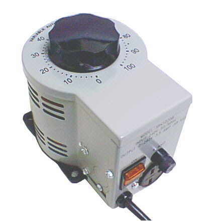
The easiest way to do this is with a 120VAC / 240VAC 50VA to 100VA Rheostat

For Test 1 the output has to be 95 VAC
For Test 2 the output has to be 208VAC
For Test 3 the output has to be 12 VAC

Output from the Rheostat that is

So I will be bench testing this weekend. It shows I have to apply 95v. What would I use to give me 95 volts for testing purposes?
 

peapvp

Well-known member
Steel Soldiers Supporter
1,115
1,232
113
Location
Basehor, KS
Phil,

unfortunately, that wont work. It's a PWM Motor Controller, not a plain Rheostat like this one here:


A cheaper way is a Rheostat

We usually use this type of Rheostat:


Wire 120VAC Phase or 240VAC Phase to one leg and connect the wiper to the input on the A11

check with meter for Voltage - start to turn up the voltage from the other leg so you should start a low Voltage until you get to the 95VAC, 208VAC or 12VAC

I posted the setup in Post #18 of this Thread:


peapvp

Well-known member
Steel Soldiers Supporter
1,115
1,232
113
Location
Basehor, KS
Phil,

On the 100 Ohm Rheostat, do not connect the second leg to Neutral or the other Phase of the 240VAC - this will draw to much current through the resistor and VA would have to be around 750VA to 1KVA
 

peapvp

Well-known member
Steel Soldiers Supporter
1,115
1,232
113
Location
Basehor, KS
Yes,

but you still can only connect the one leg to the Phase and leave the other leg open / unconnected and the wiper would be your output

A 200 Ohm Rheostat would work too, but the Output Voltage adjustment will be more difficult

With 200 Ohm and connecting both legs you would need the following VA:


I=U / R => 120VAC / 200 Ohm = 0.6 Amps => P = U x I = 120VAC x 0.6 A = 72 VA

I=U / R => 240VAC / 200 Ohm = 1.2 Amps => P = U x I = 240VAC x 1.2 A = 288 VA

A 300 VA 200 Ohm Rheostat would do the job and you would be able to connect both legs, to either L1 and N or L1 and L2

This would give you all three needed voltages.

The current draw on the Wiper for either tests is minimal, usually less then 100mA

P = U x I = 208VAC x 0.1 A = 20.8 VA plus the 288VA = 308.8 VA

A 300 VA Rheostat will be handle this for less then 5 minutes

The entire setup is easier to adjust the Output Voltage when both legs are connected

Any VA below this with less then 200 Ohm will require you to leave one leg open


Could I use 100ohm 100w rheostat?
 

pf.hal1984

Member
48
25
18
Location
Killeen Tx
Just going over some resistors. My R2 is only reading 50 ohms. It should be 510 so I know I have a bad resistor there. I'm having a hard time finding a replacement. This is the only thing I have found close to the specs." 510 Dale 55w equivelent." I know i have to change the mounting but will this work? it is 500 ohms 55 w with 5%
 

peapvp

Well-known member
Steel Soldiers Supporter
1,115
1,232
113
Location
Basehor, KS
Actually, NO - the resistor is probably OK. The Ohm reading you got is the DC Resistance of the Transformer T3 as it is connected in Parallel to R2
When two or more resistors are parralled then the combined resistance in Ohm is lower then the smallest single resistors (Primary Side T3) in such circuit

R|| = [R2 x Rt3] / [R2 + Rt3]


Just going over some resistors. My R2 is only reading 50 ohms. It should be 510 so I know I have a bad resistor there. I'm having a hard time finding a replacement. This is the only thing I have found close to the specs." 510 Dale 55w equivelent." I know i have to change the mounting but will this work? it is 500 ohms 55 w with 5%
 

pf.hal1984

Member
48
25
18
Location
Killeen Tx
Actually, NO - the resistor is probably OK. The Ohm reading you got is the DC Resistance of the Transformer T3 as it is connected in Parallel to R2
When two or more resistors are parralled then the combined resistance in Ohm is lower then the smallest single resistors (Primary Side T3) in such circuit

R|| = [R2 x Rt3] / [R2 + Rt3]
I'm not pinning it out. Im reading it tab to tab on the resistor itself. My r1 is reading 10 which it should and my r3 which is also 510.
 

peapvp

Well-known member
Steel Soldiers Supporter
1,115
1,232
113
Location
Basehor, KS
Did you desolder the wires on each end on R2?

If not, those wires connect R2 to the primary side of Transformer T3

I'm not pinning it out. Im reading it tab to tab on the resistor itself. My r1 is reading 10 which it should and my r3 which is also 510.
 

pf.hal1984

Member
48
25
18
Location
Killeen Tx
Did you desolder the wires on each end on R2?

If not, those wires connect R2 to the primary side of Transformer T3
Okay, so your right. Why can't this be easier? I removed the wires and Ta da 510. Everyone else has burned up obvious repairs. No, I have to take it to depot level repairs. I was an A3 BFVS maintainer and we never learned circuitry in my B9 ASI. This system makes me feel so dumb.
 

peapvp

Well-known member
Steel Soldiers Supporter
1,115
1,232
113
Location
Basehor, KS
It is difficult to make a prediction as to what part is not working correctly, until you do the three tests. At that point we either got a problem in A11 or it is somewhere else. But until then, we don't know.


Okay, so your right. Why can't this be easier? I removed the wires and Ta da 510. Everyone else has burned up obvious repairs. No, I have to take it to depot level repairs. I was an A3 BFVS maintainer and we never learned circuitry in my B9 ASI. This system makes me feel so dumb.
 

Guyfang

Moderator
Staff member
Moderator
16,768
24,084
113
Location
Burgkunstadt, Germany
Rule #1 in testing. ALWAYS isolate what ever you are testing for ohms. ALWAYS. We have all made this mistake at least a few times, (if not more). You are not dumb. Inexperanced, yes. Are you learning? Yes! And that is good.
 

pf.hal1984

Member
48
25
18
Location
Killeen Tx
Ok, got my rehostat in and wired to a 120 outlet. To start with test one. I apply 95v to pin A on J13 and ground to pin B on J13. Is there an easier way to do this than to put it on the pins? I have no good female pins to help me to not fry or electrocute myself.
 

peapvp

Well-known member
Steel Soldiers Supporter
1,115
1,232
113
Location
Basehor, KS
Ok, got my rehostat in and wired to a 120 outlet. To start with test one. I apply 95v to pin A on J13 and ground to pin B on J13. Is there an easier way to do this than to put it on the pins? I have no good female pins to help me to not fry or electrocute myself.
Yes, just connect them to R2 - make sure you have removed the conformal coating on the part on the voltage regulator board where you measure the results

And for test two, connect AC 208 directly on H1 and H2 of T2
 
Top