• Steel Soldiers now has a few new forums, read more about it at: New Munitions Forums!

  • Microsoft MSN, Live, Hotmail, Outlook email users may not be receiving emails. We are working to resolve this issue. Please add support@steelsoldiers.com to your trusted contacts.

MEP005A 5volts only

peapvp

Well-known member
Steel Soldiers Supporter
1,115
1,230
113
Location
Basehor, KS
Desoldere Q1. I got 167 across both legs. This diode has two legs unlike the others. If I did this right., then it's not blocking properly.
That’s an scr with one leg being the gate and the other two anode and cathode -
 

pf.hal1984

Member
48
25
18
Location
Killeen Tx
That’s an scr with one leg being the gate and the other two anode and cathode -
So I take the the threaded portion would be anode or cathode? Either way i get nothing across except by testing both legs. I take it this one is shorted out?
 

peapvp

Well-known member
Steel Soldiers Supporter
1,115
1,230
113
Location
Basehor, KS
So I take the the threaded portion would be anode or cathode? Either way i get nothing across except by testing both legs. I take it this one is shorted out?
Procedure to Test the SCR with the help of Multimeter:
  • To test the SCR, keep the Multimeter into Ohmmeter mode.
  • Connect the positive output lead of the multimeter to the anode and the negative lead to the cathode.
  • The multimeter should indicate no continuity.
  • Touch the gate of the SCR to the anode.
  • The multimeter should indicate continuity through the SCR.
  • When the gate lead is removed from the anode, conduction may stop or continue depending on whether the multimeter is supplying enough current to keep the device above its holding current level.
  • If the multimeter indicates continuity through the SCR before the gate is touched to the anode, it indicates that the SCR is shorted.
  • If the multimeter will not indicate continuity through the SCR after the gate has been touched to the anode, it indicates that the SCR is open.
 

pf.hal1984

Member
48
25
18
Location
Killeen Tx
Procedure to Test the SCR with the help of Multimeter:
  • To test the SCR, keep the Multimeter into Ohmmeter mode.
  • Connect the positive output lead of the multimeter to the anode and the negative lead to the cathode.
  • The multimeter should indicate no continuity.
  • Touch the gate of the SCR to the anode.
  • The multimeter should indicate continuity through the SCR.
  • When the gate lead is removed from the anode, conduction may stop or continue depending on whether the multimeter is supplying enough current to keep the device above its holding current level.
  • If the multimeter indicates continuity through the SCR before the gate is touched to the anode, it indicates that the SCR is shorted.
  • If the multimeter will not indicate continuity through the SCR after the gate has been touched to the anode, it indicates that the SCR is open.
JAN2N689 NSN 5961-00-226-8697
 

peapvp

Well-known member
Steel Soldiers Supporter
1,115
1,230
113
Location
Basehor, KS
Btw. did you adjust your Rheostat to 12VAC with T3 connected or did you do that before connecting to T3 - just double checking
 

peapvp

Well-known member
Steel Soldiers Supporter
1,115
1,230
113
Location
Basehor, KS
Only between C and A if G is connected with an extra wire to A while A is on your DMM Plus Lead and C on the Black Lead - you need three hands for this test - G acts like an on off switch when connecting to A
 

pf.hal1984

Member
48
25
18
Location
Killeen Tx
Btw. did you adjust your Rheostat to 12VAC with T3 connected or did you do that before connecting to T3 - just double checking
After
Only between C and A if G is connected with an extra wire to A while A is on your DMM Plus Lead and C on the Black Lead - you need three hands for this test - G acts like an on off switch when connecting to A
It works as stated by jumping a A and G. But it works both ways because C acts like it is shorted to H. All I'm doing is jumping A to G which is shorted to C. With test leads switched on both sides. There is no blocking when jumped.
 

peapvp

Well-known member
Steel Soldiers Supporter
1,115
1,230
113
Location
Basehor, KS
After
It works as stated by jumping a A and G. But it works both ways because C acts like it is shorted to H. All I'm doing is jumping A to G which is shorted to C. With test leads switched on both sides. There is no blocking when jumped.
Ok, C and G are like a Diode - however it doesn’t matter - the only two questions which matter for an SCR is that A and C are conducting when G is connected to A and it stops conducting when G is removed from A - this test has to be performed in Ohm setting on DMM not diode test
 

peapvp

Well-known member
Steel Soldiers Supporter
1,115
1,230
113
Location
Basehor, KS
After
It works as stated by jumping a A and G. But it works both ways because C acts like it is shorted to H. All I'm doing is jumping A to G which is shorted to C. With test leads switched on both sides. There is no blocking when jumped.
A SCR fails only in two ways:
1. It doesn’t turn ON at all

2. It turns on On all the time

It basically looses its ability to act like a switch or relay
 

pf.hal1984

Member
48
25
18
Location
Killeen Tx
A SCR fails only in two ways:
1. It doesn’t turn ON at all

2. It turns on On all the time

It basically looses its ability to act like a switch or relay
So this
A SCR fails only in two ways:
1. It doesn’t turn ON at all

2. It turns on On all the time

It basically looses its ability to act like a switch or relay
So this Isn't a diode? And yes, it is functioning the way it should as stated in the test. But like I said. C and G are not blocking as you say it acts as a diode. I have continuity both directions between C and G.
 

peapvp

Well-known member
Steel Soldiers Supporter
1,115
1,230
113
Location
Basehor, KS
So this
So this Isn't a diode? And yes, it is functioning the way it should as stated in the test. But like I said. C and G are not blocking as you say it acts as a diode. I have continuity both directions between C and G.
Yes, these devices work with much higher voltages as your meter and at that point C and G are blocking - they go up to 200 to 1000 VAC between A and C with only a few volts needed on G to turn on
 

peapvp

Well-known member
Steel Soldiers Supporter
1,115
1,230
113
Location
Basehor, KS
Desoldere Q1. I got 167 across both legs. This diode has two legs unlike the others. If I did this right., then it's not blocking properly.
You see you got 167 if you had a short then you would get 0 - btw how is Q2? I am on an IPhone and it makes it difficult to jump between posts
 

peapvp

Well-known member
Steel Soldiers Supporter
1,115
1,230
113
Location
Basehor, KS
You see you got 167 if you had a short then you would get 0 - btw how is Q2? I am on an IPhone and it makes it difficult to jump between posts
And SCR’s are AC devices which means they have voltage drop in either direction and in your case it 167 milli Volt
 

pf.hal1984

Member
48
25
18
Location
Killeen Tx
Yes, these devices work with much higher voltages as your meter and at that point C and G are blocking - they go up to 200 to 1000 VAC between A and C with only a few volts needed on G to turn on
So what your saying is I need an out
Yes, these devices work with much higher voltages as your meter and at that point C and G are blocking - they go up to 200 to 1000 VAC between A and C with only a few volts needed on G to turn on
I broke out my power probe and put power and ground to G. It won't switch to allow continuity.
You see you got 167 if you had a short then you would get 0 - btw how is Q2? I am on an IPhone and it makes it difficult to jump between posts
I didn't mean a short. That was my fault. I have to do Q2 tomorrow. What I'm saying is that G
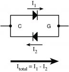
The connection between C and G looks like this here:

View attachment 788530
I have to do Q2 tomorrow. My wife is getting upset. Lol
 
Top