• Steel Soldiers now has a few new forums, read more about it at: New Munitions Forums!

  • Microsoft MSN, Live, Hotmail, Outlook email users may not be receiving emails. We are working to resolve this issue. Please add support@steelsoldiers.com to your trusted contacts.


MEP802A Temp guage not working and 2 wires cut

c5jener

New member
10
3
3
Location
Omaha, NE
Just received a nice 2008 MEP-802A - it starts and runs fine however there are 2 wires (labeled in red 126A20 & 143C20) that were not connected to anything (on the fuel side in the white wiring). The wires were initially frayed like they rubbed apart that I later clipped clean. I'm curious if these wires are the cause of my temp guage not moving / working? Any help would be greatly apprectiated.

image3.jpegimage2.jpegimage1.jpegimage0.jpeg
 

kloppk

Well-known member
Steel Soldiers Supporter
1,976
3,069
113
Location
Pepperell, Massachusetts
Those two wires are suppose to be connected to the cut off RED and BLACK wires hanging down from the Oil Pressure Switch in your last two pictures.
No they are not related to the Oil Pressure gauge not working.

Might want to check the wire from the Oil Pressure Sensor, the goldish thing with one wire on the bottom of it in your last two pictures.
It's connected to the "T" plumbing fitting on the panel with the Dead Crank Switch. It goes from there and makes it's way to the "S" terminal on the Oil Pressure Gauge.
 

Zed254

Well-known member
866
465
63
Location
S. Hampton Roads, VA
TMs are here: https://www.steelsoldiers.com/threa...-generator-and-mep-803-10kw-generator.148871/

802 and 803 are very similar machines: that link looks like it has both sets of TMs.

My 802 vibrated so bad it broke the oil pressure switch wires. You may need to add 3 or 4 inches of wire to help with the vibration dampening. TMs will help you with troubleshooting the temperature gauge. First step is to check the wires at the gauge and the sender.
 
Last edited:

c5jener

New member
10
3
3
Location
Omaha, NE
TMs are here: https://www.steelsoldiers.com/threa...-generator-and-mep-803-10kw-generator.148871/

802 and 803 are very similar machines: that link looks like it has both sets of TMs.

My 802 vibrated so bad it broke the oil pressure switch wires. You may need to add 3 or 4 inches of wire to help with the vibration dampening. TMs will help you with troubleshooting the temperature gauge. First step is the check the wires at the gauge and the sender.
When I picked up - jumped started right up with only 16hrs and I noted all the gauges were operating in normal range, however when I got home some 3 hrs and many bumps / train tracks later - I replaced the batteries and she started right up again with everything looking good. After about an hour the vibration from running and driving home must have loosened the oil pressure line on the back side of the dead crank switch spitting oil everywhere. After correcting, cleaning and adding new breakin oil she started right up again - this time with no temperature reading on the control panel. Guess I'll tighten connections and see if I just don't have a loose wire somewhere.
 

c5jener

New member
10
3
3
Location
Omaha, NE
Those two wires are suppose to be connected to the cut off RED and BLACK wires hanging down from the Oil Pressure Switch in your last two pictures.
No they are not related to the Oil Pressure gauge not working.

Might want to check the wire from the Oil Pressure Sensor, the goldish thing with one wire on the bottom of it in your last two pictures.
It's connected to the "T" plumbing fitting on the panel with the Dead Crank Switch. It goes from there and makes it's way to the "S" terminal on the Oil Pressure Gauge.
My oil pressure is fine, just my temp gauge is not working. You don't happen to know which wire goes to which by chance - I'm having trouble locating those wires in a diagram. Thanks
 

kloppk

Well-known member
Steel Soldiers Supporter
1,976
3,069
113
Location
Pepperell, Massachusetts
Sorry bout that, was thinking OP gauge.
The Coolant Temp Sensor is MT6 in the schematics.
The wire connected to it is 129Axx
It goes to Connector P7 pin 2.
In turn it's connected to J7 pin 2.
J7 pin 2 is connected to wire 129Bxx which then runs to the Temp gauge (M6) "S" terminal.
 

Attachments

c5jener

New member
10
3
3
Location
Omaha, NE
The red and black wires to the oil pressure switch should be connected. Here's a pic of mine before I added the extra wire: this configuration was too tight and vibrated loose.
Thanks Zed - can you tell me what numbered wires you have going to your red and black wires on oil pressure sensor/switch? Do you know If my coolant gauge is not working correctly if that would prevent genset from running? Since it has a high temp shutoff im not sure if it needs a signal (low temp) to start or just a high temp signal to shutdown...?? Thanks -Chris
 

Zed254

Well-known member
866
465
63
Location
S. Hampton Roads, VA
Thanks Zed - can you tell me what numbered wires you have going to your red and black wires on oil pressure sensor/switch? Do you know If my coolant gauge is not working correctly if that would prevent genset from running? Since it has a high temp shutoff im not sure if it needs a signal (low temp) to start or just a high temp signal to shutdown...?? Thanks -Chris
Sorry, my 802 is located at my timber farm. If the worn wires were near the oil switch, it's a good bet that they should be connected there. Coolant gauge problems can be the gauge, the sender, the wiring connections. One of my coolant gauges had a lot of nicks in it...from operators tapping on it with a tool to get the needle moving. It lasted until I tapped the glass and broke it....so my problem was the gauge. It should not affect engine operation. Look at those TMs for troubleshooting guide. I also had sluggish response on the fuel gauge when filling it - if you see this reach in the tank and move the floats up and down on the sender....and check that there is no crud in the bottom of the fuel tank. This can affect your Aux fuel pump operation - one sender is for the gauge and one is for the Aux pump switch.
 

Daybreak

2 Star Admiral
Steel Soldiers Supporter
1,521
741
113
Location
Va
Howdy,
Pictures say a lot. :)

You will want to replace all the fuel return lines. I see they are old, and are weeping.
How much water is in that fuel tank?
How much water and crude is in that oil?

Start from the ground up and get everything is good shape before running.

MEP-802A MEP-803A Filters and Parts
start here,
2nd post has quick links to many things of importance.
3rd has links to the manuals.

good luck.
 

Guyfang

Moderator
Staff member
Moderator
15,891
22,159
113
Location
Burgkunstadt, Germany
It doesn't matter which wire you hook to the red or black wire.

The Temp gauge not working will have no effect on the generator operation.
Correct.
But if you want to hook it up as per the schematic,
OP-C gets wire # 143C
OP-NC gets wire #126A

Edit: typo
 
Last edited:

c5jener

New member
10
3
3
Location
Omaha, NE
Sorry bout that, was thinking OP gauge.
The Coolant Temp Sensor is MT6 in the schematics.
The wire connected to it is 129Axx
It goes to Connector P7 pin 2.
In turn it's connected to J7 pin 2.
J7 pin 2 is connected to wire 129Bxx which then runs to the Temp gauge (M6) "S" terminal.
Good Afternoon,

Got back to working on things after holidays - thinking I may have a bad temp sensor or thermostat is stuck open. Checked continuity from connector on MT6 to the "S" Terminal on the gauge and its good. I did swap out the temp gauge as well with same results (no temp). Anything I may have forgotten?

Thanks,
Chris
 

kloppk

Well-known member
Steel Soldiers Supporter
1,976
3,069
113
Location
Pepperell, Massachusetts
With S1 in the RUN position check M6 Terminal "I" (eye) to be sure ~24 VDC is present.
Also check that M7's mounting bracket is connected to chassis ground.
If that all checks out then I suspect you have a bad sender.

With S1 in the RUN position measure the voltage at the Temp Senders terminal.
Here are some approximate voltages you should see there.
100F 8.0 VDC
140F 6.2 VDC
160F 5.3 VDC
180F 4.3 VDC

If the voltage at the Temp sender is at ~24 VDC then the Temp Sender would appear to be shot.
 

c5jener

New member
10
3
3
Location
Omaha, NE
With S1 in the RUN position check M6 Terminal "I" (eye) to be sure ~24 VDC is present.
Also check that M7's mounting bracket is connected to chassis ground.
If that all checks out then I suspect you have a bad sender.

With S1 in the RUN position measure the voltage at the Temp Senders terminal.
Here are some approximate voltages you should see there.
100F 8.0 VDC
140F 6.2 VDC
160F 5.3 VDC
180F 4.3 VDC

If the voltage at the Temp sender is at ~24 VDC then the Temp Sender would appear to be shot.
Just saw so will try next, I did find a previous post regarding testing temp sender and it started off @ around 330 Ohms then decreased as the temp increased which would make me think sender is good & thermostat may be stuck open or missing.

"
Check TM for testing procedure.....bottom of post:


2-92 COOLANT TEMPERATURE SENDER.
NOTE
Engine must be cool when performing this test
2-92.1 Testing.
a Shut down generator set
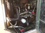
b. Open left side engine access door
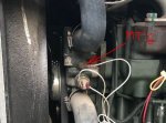
c. Disconnect and tag electrical lead from coolant temperature sender (4, FIGURE 2-25)
d. Set multimeter for ohms and connect to coolant temperature sender terminal and casing. Multimeter indication
should be greater than 300 ohms.
e. Start generator set and observe multimeter.
f As engine operates and coolant temperature rises, multimeter indication should decrease,
g. Shut down generator set.
h Replace coolant temperature sender if indications are other than above
i. Connect electrical lead, remove tag, and dose left side engine access door.
2-92.2 Removal.
a Shut down generator set
b Open left side engine access door and disconnect negative battery cable
c Tag and disconnect temperature sender (4, FIGURE 2-25) lead.
d Unscrew temperature sender (4) from thermostat housing.

ARMY TM 9-6115-642-24"
 

c5jener

New member
10
3
3
Location
Omaha, NE
With S1 in the RUN position check M6 Terminal "I" (eye) to be sure ~24 VDC is present.
Also check that M7's mounting bracket is connected to chassis ground.
If that all checks out then I suspect you have a bad sender.

With S1 in the RUN position measure the voltage at the Temp Senders terminal.
Here are some approximate voltages you should see there.
100F 8.0 VDC
140F 6.2 VDC
160F 5.3 VDC
180F 4.3 VDC

If the voltage at the Temp sender is at ~24 VDC then the Temp Sender would appear to be shot.
Thanks for the assist

So with the S1 in Run - I'm getting 26VDC @ terminal "I" of M6, confirmed that M7 mounting bracket is connected to chassis ground. The voltages of the Temp Sender terminal were 7.5 VDC and decreasing - so I'm almost sure sender is good. However with those voltage readings my gauge should be registering within the registered temp range on gauge but it is not... 🤬 Starting to wonder what the chances are my secondary temp gauge is broke as well.


Update - so with all the info I had it made no sense not working so I pulled out my second spare temp meter and it worked............. Onto the rest of the adventure. Thanks all for the input - really helped!
 
Last edited:
Top
AdBlock Detected

We get it, advertisements are annoying!

Sure, ad-blocking software does a great job at blocking ads, but it also blocks useful features of our website like our supporting vendors. Their ads help keep Steel Soldiers going. Please consider disabling your ad blockers for the site. Thanks!

I've Disabled AdBlock
No Thanks