

horseman8m
New member
- 4
- 0
- 1
- Location
- Lake Park, GA
I Installed a wireless starter circuit on my mep803 so now i don't have to leave the house to run the generator.
updated the circuit page below.
https://youtu.be/z098G0Nuzgw
the motorcycle alarm with engine start, circuit ,, wire into diagram.


the antenna is off to the side so the door doesn't hit it.
The blue wire from the alarm/start block goes to antenna.


the wire bundle from the alarm/start block,, red-black to 12v pwr supply.
Orange wire goes to channel 1 and channel 3 trigger.
Blue wire goes to the channel 2 (starter) trigger.

protected from weather and wire tied to side wall when done testing.


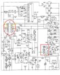
the timer circuit has 3 channels,,
first channel (on left) has to turn on fuel at the S1 switch and run. connection 3and 4 .
second channel (center) has a delay that powers the starter for 10 seconds then turns off. connection 7and 8 .
the third channel (on the right) has a delay of 27 seconds then turns on for about 3/4 of a second then turns off, this is to energize the field witch keeps itself going after. S5 = switch - connect to 5 and 6.
S1 = switch 1

connect channel one red wire to 3, and channel two red wire to 7.

connect channel one black wire to 4, and channel two black wire to 8.

S5 = switch 5

connect channel 3 wires to 5 and 6

power supply wires through firewall before epoxy.
vibration will short out your wires.

12vdc power supply
3A fuse between supply and firewall on red wire.

updated the circuit page below.
https://youtu.be/z098G0Nuzgw
the motorcycle alarm with engine start, circuit ,, wire into diagram.
the antenna is off to the side so the door doesn't hit it.
The blue wire from the alarm/start block goes to antenna.
the wire bundle from the alarm/start block,, red-black to 12v pwr supply.
Orange wire goes to channel 1 and channel 3 trigger.
Blue wire goes to the channel 2 (starter) trigger.
protected from weather and wire tied to side wall when done testing.
the timer circuit has 3 channels,,
first channel (on left) has to turn on fuel at the S1 switch and run. connection 3and 4 .
second channel (center) has a delay that powers the starter for 10 seconds then turns off. connection 7and 8 .
the third channel (on the right) has a delay of 27 seconds then turns on for about 3/4 of a second then turns off, this is to energize the field witch keeps itself going after. S5 = switch - connect to 5 and 6.
S1 = switch 1
connect channel one red wire to 3, and channel two red wire to 7.
connect channel one black wire to 4, and channel two black wire to 8.
S5 = switch 5
connect channel 3 wires to 5 and 6
power supply wires through firewall before epoxy.
vibration will short out your wires.
12vdc power supply
3A fuse between supply and firewall on red wire.
Last edited:
")