• Steel Soldiers now has a few new forums, read more about it at: New Munitions Forums!

  • Microsoft MSN, Live, Hotmail, Outlook email users may not be receiving emails. We are working to resolve this issue. Please add support@steelsoldiers.com to your trusted contacts.

MEP803A fuel level adjustment

Daybreak

2 Star Admiral
Steel Soldiers Supporter
1,522
771
113
Location
Va
I was just reading a post by Zarathustra "NO FUEL error on 802a/803a when there is actually fuel in the tank" from 2015. He gives an excellent description of the low fuel sensor. He also states that the holes in the gasket are not evenly spaced. That was my feeling as well. I don't think it is a SAE 5 hole spacing.The screws on both the low fuel sensor and the fuel level sensor were on a tilt and cross threaded when I took them apart. When I retapped the holes and tried to install them the one screw went in fine but the rest would only go in on an angle. I kept rotating the sensor and trying to get the screws in without cross threading. I finally found an orientation where all the screws went in straight with no crossthreading. I think there is only one position where all the screw holes line up.
Howdy,
A SAE 5 hole is NOT evenly spaced. :)

It's like a puzzle. You have to hold the gasket and keep trying it a bunch of different ways, until... bingo, the right hole alignment.
 

Guyfang

Moderator
Staff member
Moderator
16,766
24,074
113
Location
Burgkunstadt, Germany
I was just reading a post by Zarathustra "NO FUEL error on 802a/803a when there is actually fuel in the tank" from 2015. He gives an excellent description of the low fuel sensor. He also states that the holes in the gasket are not evenly spaced. That was my feeling as well. I don't think it is a SAE 5 hole spacing.The screws on both the low fuel sensor and the fuel level sensor were on a tilt and cross threaded when I took them apart. When I retapped the holes and tried to install them the one screw went in fine but the rest would only go in on an angle. I kept rotating the sensor and trying to get the screws in without cross threading. I finally found an orientation where all the screws went in straight with no crossthreading. I think there is only one position where all the screw holes line up.
That's why it important to mark the orientation of the holes, before taking it off. That way it is a snap to put it back in.
 
Last edited:

dav5

Active member
396
183
43
Location
Mono, Ontario
Thanks Guyfang I would have followed your advice and marked it but all the screws on both senders were only part way in and on an angle with the black goo sealing them so I knew the plates weren't oriented right before I took them off. I learned a lot doing this and now even know what a SAE 5 gasket is!!!!
All the assistance is greatly appreciated. Knowing there is expert help available sure gives me the confidence to tackle stuff I probably wouldn't normally.
 

dav5

Active member
396
183
43
Location
Mono, Ontario
OK, let's get started.

First, I am going to see if the TM I uploaded is older than the one I am referring you to. If so, I will upload a newer version.

Second, yes you can get the float out. It's a PITA. But it can be done. If your arms are not as big as Man Mountain Dean, reach in with one arm, and push the float out of the hole, while pulling with the other. And you have to turn the switch one way or the other at the same time.

This appears to be a new style tank. The old ones did not have metal mating surfaces on the top of the tank. It was plastic, with nuts imbedded in the plastic. The upgrade was because of too many leaks and seeps. And it looks like the sending unit is smaller then what I remember. Or your hands are bigger?

You will hate yourself for forty forevers if you try and take the slanted panel off. In the end, you will probably take the entire front end off easier. But, be my guest!

Trust me, the float comes out without jumping through all those hoops. The TM will NOT explain it in detail. Post a picture of the float when you have it out.

Just checked. The problem with the manual is that the new book is dated 2012, BUT its classified C. That means we can not post it in SS. Or give it away. Sorry.
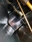
Hi, I thought I had my fuel level problems solved but yesterday it acted up again. I tried to force my arm into the tank via the filler hole to feel where the float was but after losing some skin I realized that it just wasn't going to happen. I prefer to think of my arms as muscular but I guess maybe they are just fat. Anyway I decided to stick my expensive cell phone down the hole and I actually got a pretty good photo plus I was able to get the phone back out without losing it. You can see the fuel level sensor and the inside view of the well nut. The float was oriented towards the right hand wall of the tank which was not where I originally placed it. I was able to twist the sender counterclockwise while the screws were still tight. As Guyfang stated there is a metal insert in the tank that isn't there on earlier models. This insert isn't fixed in place even when the screws are tightened with the gasket in place. I tried to twist the low fuel sensor and it does the same thing. So if your sensors aren't working I would check the orientation of the sensors if you have a newer model [mine is a 2006]IMG_20170721_141517.jpg
 

csheath

Active member
714
213
43
Location
FL
Trying to weasel mine out the hole right now. It quit working after I pumped the tank dry to rotate the fuel. I have performed the gauge check and confirmed the gauge is okay. I have checked the wires and they are okay so problem is in the sending unit. By checking the wires I mean one has continuity to ground and the other has continuity from the sending unit to the S terminal. I'm about to go back out and see if I can exercise the float with the thing hanging in the hole. If that doesn't work I guess I will remove the carriage bolt as you did. My tank is all plastic.

My wire going to the S terminal was on one of the sending unit mount screws. I assume it doesn't matter which wire goes where on the unit since it has a plastic tank. It will read the same resistance either way.
 

Light in the Dark

Well-known member
Steel Soldiers Supporter
3,828
5,938
113
Location
MA
Hi, I thought I had my fuel level problems solved but yesterday it acted up again. I tried to force my arm into the tank via the filler hole to feel where the float was but after losing some skin I realized that it just wasn't going to happen. I prefer to think of my arms as muscular but I guess maybe they are just fat. Anyway I decided to stick my expensive cell phone down the hole and I actually got a pretty good photo plus I was able to get the phone back out without losing it. You can see the fuel level sensor and the inside view of the well nut. The float was oriented towards the right hand wall of the tank which was not where I originally placed it. I was able to twist the sender counterclockwise while the screws were still tight. As Guyfang stated there is a metal insert in the tank that isn't there on earlier models. This insert isn't fixed in place even when the screws are tightened with the gasket in place. I tried to twist the low fuel sensor and it does the same thing. So if your sensors aren't working I would check the orientation of the sensors if you have a newer model [mine is a 2006]View attachment 690999
Great shot... thanks for this. My 803A has what I believe to be a stuck or an otherwise incorrect fuel reading. Good to see the inside as I DO have Moutain Man Dean forearms. I can at least approximate what the linkage is doing now based off of it. Thank you.
 

csheath

Active member
714
213
43
Location
FL
I ended up having to scribe everything and take the plate off the sender then I fished the sending unit out of the filler neck. After I got it out I tried to assemble and insert it back in through the tank hole and it would not go no way no how. I took it back apart and fished it back in through the filler neck with a wire attached to pull it up in the hole and reassembled the unit in the hole.

At the end of the day mine must have just had a bad connection that coincidentally showed when I pumped the fuel out. I wasn't getting any correct ohm reading even with it loose in the hole and the ohm meter connected with alligator clips. (that's roach clips to you guyfang) Anyway it indicated a bad sending unit but once out of the tank it had the correct readings at both ends of the sweep. I cleaned it all up and put it back in and the gauge is working again. I did go ahead and reverse the wires just because a normal unit would have the sensor wire to the sensor post.
 

dav5

Active member
396
183
43
Location
Mono, Ontario
I hope it works for you. I did the same thing. Checked the ohm reading and it was fine and reinstalled it. It worked well for awhile but then it started to do the same erratic readings. This is a fantastic site. I searched the NSN on Google and it came back to a post on here from about a year and a half ago. Since I am totally computer illiterate I can't send you the link unfortunately. The exact same sending unit is available on Amazon for $38 [h=1]Auto Meter 3262 Universal Fuel Level Sender .[/h]
 

dav5

Active member
396
183
43
Location
Mono, Ontario
Also there is a very good post about removing the sender. You have to take it apart to install it without bending it.
I haven't received my sender yet and will be at my camp for an extended period so I can't verify if it is the right sender but the specs are the same and it looks identical.
 

zarathustra

Active member
Steel Soldiers Supporter
235
59
28
Location
glasgow,ky
The way I found to get the correct orientation is not to orient the sender, but the gasket. It is much easier to see the gasket and how that orients. Once you've nailed down the gasket orientation you can use a marker to mark the position of the gasket vis a vis the tank. Mark the tank in the same place. It can only go on one way. Then match the gasket to the sender and mark where the mark on the gasket aligns with the sender. Then match up all three marks and you're home free!

Getting the float unit into the tank is another problem. I've removed one of the float arm mounting screws / bolt --- fitted it into the tank and re installed the screw/bolt with the float arm in the tank. If one has large hands this is impossible......

Remember that the only thing the float does is send a signal to the gauge. The "no fuel" fault comes from that other piece (liquid level sensor - left front of the tank) and that is easily adjustable. Just as a note... if you disconnect that four pin connector from the liquid level sensor you will lose the "no fuel" error signal.

However if the connector is disconnected and you ever try to use the AUX FUEL pump you'll end up with diesel fuel all over the place 'cause the signal to shut off the fuel pump (tank full) also travels through that connector so the unit will never "think" that the fuel tank is full.

good luck
z
 
Last edited:

dav5

Active member
396
183
43
Location
Mono, Ontario
Zarathustra, I am happy to see you back I have learned a lot from your posts. I figured out the no fuel issue and set the sensor to 1/16 off the bottom which fixed that problem. I had all the fuel sender gasket holes lined up and installed it properly but there is a metal ring in the new tanks and it is not fixed so with not too much pressure it rotates freely which changes the float orientation
 

dav5

Active member
396
183
43
Location
Mono, Ontario
I ended up having to scribe everything and take the plate off the sender then I fished the sending unit out of the filler neck. After I got it out I tried to assemble and insert it back in through the tank hole and it would not go no way no how. I took it back apart and fished it back in through the filler neck with a wire attached to pull it up in the hole and reassembled the unit in the hole.


Great idea to fish it through the fill hole. I removed my sensor and pulled it back through the fill hole with a string attached. I am picking up my new sensor on Tuesday. I measured the length of the sensor with the float down and it is only about 8.5 inches. The tank depth is about 10.5 inches so it will read empty with 2 inches of fuel in the tank. Can anyone give me the dimensions of the sensor. I need the distance from the mounting plate to the center of rotation of the float and the distance from the center of rotation to the end of the float. Thanks. Ted
 

dav5

Active member
396
183
43
Location
Mono, Ontario
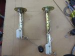
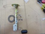
I picked up my new Amazon fuel level sender. It is identical to the original except that it is longer. It can be adjusted to fit quite easily. It comes with 3/16 half inch bolts that in my opinion are better than the Philips head original screws. There are no nuts on the backside like the original but they are the same size as the nuts for the sheet metal on the generator. I am enclosing the directions. The original sensor was adjusted way shorter than the new directions suggest The tank is 10 1/2 inches deep and I think they will fit in and not hit the 45 degree wall in the tank. I was going to take off the filler neck and install it so I can reach in and lift the float to see if it binds but I am waiting until I receive the brass wellnut replacement that boatman suggested. An update may take awhile. The Walleye trip is next week and then there is moose hunt season and then there is the deer hunt. Yes GuyfangIMG_0741.jpgIMG_0743.jpgView attachment Scan0004.pdfView attachment Scan0005.pdf there are photos.
 

Daybreak

2 Star Admiral
Steel Soldiers Supporter
1,522
771
113
Location
Va
Howdy,
Can you cobble together using the old and put the new pieces on it?
 
Top
AdBlock Detected

We get it, advertisements are annoying!

Sure, ad-blocking software does a great job at blocking ads, but it also blocks useful features of our website like our supporting vendors. Their ads help keep Steel Soldiers going. Please consider disabling your ad blockers for the site. Thanks!

I've Disabled AdBlock
No Thanks