• Steel Soldiers now has a few new forums, read more about it at: New Munitions Forums!

  • Microsoft MSN, Live, Hotmail, Outlook email users may not be receiving emails. We are working to resolve this issue. Please add support@steelsoldiers.com to your trusted contacts.

MEP805-A Troubleshooting Low VAC Output

troutbum007

New member
3
0
0
Location
Traverse City Michigan
I have been tasked with troubleshooting a pair of MEP805-A Generators, which are both running fine (and at correct frequencies), but will only make very low AC Voltage...The average L-L VAC between the two is about 18, and the average L-N VAC is about 30...and these readings are consistent across all 3 phases, which in my experience, generally rules out faulty diodes in Rotating Rectifiers, Exciter Stators or AVR's...So Per the DS (24) Manual, this condition otherwise only indicates either faulty Power Potential Transformers, or faulty Generator Stator Housing Assemblies...Both units have been in a fairly damp humid environment near ocean for an extended time, without exercise...Anyone else ever experience these odd issues, and where could I even buy the parts required to fix?
 

Attachments

Guyfang

Moderator
Staff member
Moderator
16,254
23,030
113
Location
Burgkunstadt, Germany
Have you, or anyone else, seen these sets ever work right? Reason being, the probability of two different sets having the same problem at the same time, is pretty small.

Did the fault indicator, indicate an under voltage situation?

Now if I remember right, The A7, Freq Transducer needs 120 volts to work properly. Try measuring at the input terminals, (L&L, can't mix that up!) of the A-7 to see if you get 120 volts input voltage. Or try measuring directly from the TB-1, before the K-1, just to make sure of the main gen output. Terminal 2 and 13 are the AC inputs to the A-7. Whatever is easier.

When looking for parts, I would put the NSNs into my browser, and see what comes up. Also, several members of SS have bought 400 hertz machines, for parts. Some parts are interchangeable, though I don't think it may help here. Need to see.
 

troutbum007

New member
3
0
0
Location
Traverse City Michigan
Yes sir...A little background...I work for a company which is also a DoD Contractor and while I'm in Michigan, these US Army owned Generators are in Japan, so getting to the cause of problems has been difficult...None of the original crew remains on site, so background is less than reliable, but I am also told these worked correctly during day usage, for a couple of weeks...Then would immediately display the Under Voltage Fault light, upon start up...I too was puzzled with both of these having the same faults, while initially having and electrician perform basic troubleshooting steps, that I was directing over the phone...Only two common "pilot error" operator mistakes were revealed while discussing background,

1.) when I had him send photo's, I saw that the Neutral and A Phase Cables were mixed up on the Output Terminal Board (this could have made a real mess if hit with a big load!)...and

2.) He revealed that when attempting to "jump" due to start a low battery, they likely put cables in parallel, instead of series...thereby likely running 36-38 VDC through DC system...

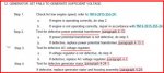
Not successfully solving the problems over the phone (electrician was not very cooperative and may have been the one that mixed output cables too), I took the long trip (Japan) to visit these Generators personally (had other business at site), but only had a short time (1/2 Day) to troubleshoot, and very few tools at site...So having inspected and seeing/smelling no burnt cables from Stator to Reconnection Panel, then to TB2, when I tested the output values and noted the low VAC values, it was at the Output Terminal Board (where it matters most), while running in Battle Short, because the Circuit Interrupter wouldn't hold otherwise due to the Low Voltage Fault. (and see that I have the L-L and L-N values reversed in my original post)

As stated originally too, both of these units have been in a pretty wet/humid environment, for quite some time, and therefore display appreciable corrosion/electrolysis at terminations...Neither VAC Meter, or Frequency Meter (Hertz) work correctly, but I was able to measure at Hz AVR and verify correct RPM's from engine, and adjust same up and down, with Frequency Adjust Potentiometers, on both units...And incidental to your kind response, the Frequency Transducer in not mentioned in the Troubleshooting guide for either No or Low Voltage Output...so I didn't test it.

So I've recommended that the Contractor try to wash their hands of these, should never have accpted responsibility in the first place...And owning unit should send to Depot for re-set...but the "client" wants a ECOD/R...and being that I wasn't able to definitively isolate the problems (feeling rather defeated), I have to take the "shotgun approach" with parts...IE buy and replace all possible culprits...

I did run NSN's through Google the other day, and had just two vendors pop that allowed me to submit RFQ's...One seemed to specialize in AC Alternator parts, and the other with such as the Voltage Potential Transformer and AVR...And unfortunately one of these vendors (wbparts.com) just replied back with a strange response, asking "How soon do you need parts?" and "what is your target price?"...So I guess I should prepare to be disappointed more, to learn that there appears to be no reliable parts source for these?

Sigh...
 

Guyfang

Moderator
Staff member
Moderator
16,254
23,030
113
Location
Burgkunstadt, Germany
Oh man. What a mess.

How did the personnel try to jump the sets? Not with a NATO slave cable I guess? And that would be approx 48 volts I think. Oh, not good. I would assume, and that's a real good way to get in trouble, but I would assume that no one has contacted the local CECOM Rep in Japan? If these are government owned, then CECOM should be able to help with troubleshooting and parts.

The reason I asked you to check at the Freq. Transducer was to verify what the actual output of the main AC is. You say the AC volt meter and the Hertz meter do not work correctly, so once again I have to assume , indeed, the main gen is not lighting off. Its always a better idea to take voltage measurements before the K-1. The K-1 relay/output contactors are world famous for filling up with water. When they rust up, the result is no output, or partial output. You have said that the units look like the environment have affected them, and this would be a classic fault.

With an ECOD, the "client" covers his butt. Can put the blame anyplace but on his own shoulders.

Can you have someone test the A-1, (volt reg) at terminals 1&3? See if the A-1 is sending voltage down to the main gen to light it off? That is one component, (the A-1) that would NOT like 48 volts. But not the only one. I could probably work up a short list if that's what you need/want.

There are probably people in this forum who have the parts you need, but I could not tell you who. If you can get CECOM to help you, it would probably go better/faster.

Sorry it took so long to get back to you. We are organizing our Thanksgiving dinner for all the expats here in my area, and its here in my house. Chaos to say the lest. I will be glad when this day is over! I at least got to choose the beer!
 

troutbum007

New member
3
0
0
Location
Traverse City Michigan
Hope you had a fine Thanksgiving sir...

No the knuckleheads on site wouldn't even know about the NATO slave cable/receptacle...and from what I gather, they added a battery into the 2 x 12 VDC batteries in series mix, by paralleling the third to one of the two in series...yeah

I obviously didn't get to troubleshoot as thoroughly as I'd have liked while on site, due to time constraints and lack of tools and a power supply...And not having any real experience with these 805-A's, I also only had the TM troubleshooting guide to work with...So again, the AC Circuit Interrupter (K1) (like the Frequency Transducer) was not on the schedule of components to check, but appeared and sounded like it was functioning properly, albeit while in Battle Short due to the Low Voltage Fault otherwise tripping it, as it should have...Seems too if "full of water", hard to imagine it not welding up when closed...Can track with zero output...but can't imagine output of any AC with this component failing, particularly evenly across all three phases as indicated at Output Terminals...

Sure wish I had some CECOM guys to bring a couple of AVR's to site, so that they could either save the day or be eliminated as at fault...They helped out with parts on occasion in Afghanistan and Iraq...Never met one that really knew much though haa...Trouble is too (at least in my mind), that while both A1's failed IAW troubleshooting specs, if the T1 Voltage Potential Transformers are bad, that could/should/would also cause the AVR's to appear faulty...I tested A1's myself, and wire 141A+ and Terminal 3- provided 6.9VDC (within spec)...But the VAC test at Terminals 10 and 11 of course indicated way low...as did the OHM tests disconnecting wire 137A, and checking Terminal 4- to Terminal 5+...

Another issue is that what ever parts need purchased, they have to come as new and through a source qualifying as a "vendor", being these Generators are still Military/DoD owned...I'm going to lean forward on the CECOM idea...In the mean time; thank you for all of your kind insights with this!
 

Guyfang

Moderator
Staff member
Moderator
16,254
23,030
113
Location
Burgkunstadt, Germany
Hope you had a fine Thanksgiving sir...

No the knuckleheads on site wouldn't even know about the NATO slave cable/receptacle...and from what I gather, they added a battery into the 2 x 12 VDC batteries in series mix, by paralleling the third to one of the two in series...yeah
I have almost 28 years experience working on Military power generation, and have never heard of anyone doing something like this. But sometimes peoples ability to do stupid things can amaze you.

I obviously didn't get to troubleshoot as thoroughly as I'd have liked while on site, due to time constraints and lack of tools and a power supply...And not having any real experience with these 805-A's, I also only had the TM troubleshooting guide to work with...So again, the AC Circuit Interrupter (K1) (like the Frequency Transducer) was not on the schedule of components to check, but appeared and sounded like it was functioning properly, albeit while in Battle Short due to the Low Voltage Fault otherwise tripping it, as it should have...Seems too if "full of water", hard to imagine it not welding up when closed...Can track with zero output...but can't imagine output of any AC with this component failing, particularly evenly across all three phases as indicated at Output Terminals...
This particular type of relay, can indeed fill up with water. There is a wonderful thread in SS that describes what happens, and how to (sometimes) correct the problem. Often, you can hear and feel the K-1 close, and have no output, output on one or two phases, or very small amounts of voltages, (3-15 volts) when the contacts in the relay do not properly close, or only make a slight contact. We had the same type relay on the MEP-004 through MEP-007A, and the problem plagued from the 70's through 90's, when the first TQG's began to be issued. And it still isn't fixed.


Sure wish I had some CECOM guys to bring a couple of AVR's to site, so that they could either save the day or be eliminated as at fault...They helped out with parts on occasion in Afghanistan and Iraq...Never met one that really knew much though haa...Trouble is too (at least in my mind), that while both A1's failed IAW troubleshooting specs, if the T1 Voltage Potential Transformers are bad, that could/should/would also cause the AVR's to appear faulty...I tested A1's myself, and wire 141A+ and Terminal 3- provided 6.9VDC (within spec)...But the VAC test at Terminals 10 and 11 of course indicated way low...as did the OHM tests disconnecting wire 137A, and checking Terminal 4- to Terminal 5+...
The T-1 are a hardy part. Rarely go bad. That two would go bad at the same time is almost beyond belief, but, it cannot be ruled out without testing. The A-1 on the other hand, were a problem early on, and didnt have a really track record. I would have loved to see MTBF info on these sets! There are a few CECOM guys who are VERY good. But yeah, sometimes you got to look far and wide for them.

Another issue is that what ever parts need purchased, they have to come as new and through a source qualifying as a "vendor", being these Generators are still Military/DoD owned...I'm going to lean forward on the CECOM idea...In the mean time; thank you for all of your kind insights with this!
Take care and wish you luck!
 
Top