- 18,145
- 27,263
- 113
- Location
- Burgkunstadt, Germany
Is this set new to you? Have you ever seen it run right?
Steel Soldiers now has a few new forums, read more about it at: New Munitions Forums!


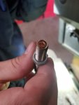
It's new to me yeah. Another mechanic has worked on it here but no one knows anything about generators. I think I found the problem though. The mpu looks messed up it has a thin copper rats nest on the tip. Other MPUs I've dealt with would prevent the Gen set from starting so this is new to me.Is this set new to you? Have you ever seen it run right?
I've never even had to replace main gen here. I usually get stuck with the ones that don't run.Apples and oranges. The gen set is a MEP-805A.
But the main gen, can be, I have seen it twice, I have heard about it many more times, a 400 hertz main gen. The problem being, that the -24P for the MEP-005A is wrong. It mixed up the NSN's between the 60 hertz and the 400 hertz. Thats what I meant.
Still no luck. I checked all over the right side with my bore scope and didn't see any data plate. Its got 140 hours on the gauge and tge generator looks crusty and old.. no signs of the panel being ever pulled.the Frequency won't adjust and gauges m8, m9, m1, don't have readings. Of course the undervoltage light is on. Any ideas?IF the MPU is not the problem, take the rear panel off the gen set and on the right side of the main gen is a data plate. See what it says.
Yeah mine said 1-1.5VACDid you adjust the depth of the MPU per the -24 TM and verify it was putting out 2-3 volts AC?
Is that extremely important as it ran before with the old MPU and the tip was worn offDid you adjust the depth of the MPU per the -24 TM and verify it was putting out 2-3 volts AC?
Yes it is.Is that extremely important as it ran before with the old MPU and the tip was worn off
Makes me wonder what the hell I was reading. Well it's almost quitting time. I'll jack with this some more later.Yes it is.
Here is the TM adjustment Procedure...
ADJUSTMENT
1. Release control panel by turning two fasteners and lower control panel slowly.
2. Disconnect wire 147C from terminal 16 and wire 148C from terminal 17 of governor control unit (WP 0043,
Figure 1, Item 56).
3. Set multimeter for ohms and connect to ends of disconnected wires 147C and 148C. Multimeter should
indicate between 800 and 900 ohms.
4. Leave multimeter connected to wires 147C and 148C and set multimeter for AC volts.
5. Crank engine with DEAD CRANK switch (WP 0110, Figure 1, Item 11) and observe multimeter. Multimeter
indication should be between 2.0 and 3.0 VAC.
CAUTION
Do not adjust magnetic pickup (6) inward more than one eighth turn each time or damage to
magnetic pickup may result.
6. To adjust output voltage in Step 5 above, loosen locknut (6A) and turn magnetic pickup (6) in no more than
one-eighth turn at a time to increase or decrease output voltage. Tighten locknut (6A).
7. Repeat Steps 5 and 6 above until proper output voltage is achieved.
8. Remove multimeter and connect wires to governor control unit.
Testing at the GCU I got 978ohms. A bit high I guess. VoltsAC is leaving me with .3-.4. The signal is not even close to correct. Thanks for keeping me honest. I'll attempt adjustment until I see a proper readingYes it is.
Here is the TM adjustment Procedure...
ADJUSTMENT
1. Release control panel by turning two fasteners and lower control panel slowly.
2. Disconnect wire 147C from terminal 16 and wire 148C from terminal 17 of governor control unit (WP 0043,
Figure 1, Item 56).
3. Set multimeter for ohms and connect to ends of disconnected wires 147C and 148C. Multimeter should
indicate between 800 and 900 ohms.
4. Leave multimeter connected to wires 147C and 148C and set multimeter for AC volts.
5. Crank engine with DEAD CRANK switch (WP 0110, Figure 1, Item 11) and observe multimeter. Multimeter
indication should be between 2.0 and 3.0 VAC.
CAUTION
Do not adjust magnetic pickup (6) inward more than one eighth turn each time or damage to
magnetic pickup may result.
6. To adjust output voltage in Step 5 above, loosen locknut (6A) and turn magnetic pickup (6) in no more than
one-eighth turn at a time to increase or decrease output voltage. Tighten locknut (6A).
7. Repeat Steps 5 and 6 above until proper output voltage is achieved.
8. Remove multimeter and connect wires to governor control unit.
I'm having a hell of a time with this MPU. I've broke 2 now not including the one that was in it. The one I got in it right now I could only adjust to 1.1vac. While it's running I can measure 5.4vac across terminal 16/17. Is this where it's supposed to be?Yes it is.
Here is the TM adjustment Procedure...
ADJUSTMENT
1. Release control panel by turning two fasteners and lower control panel slowly.
2. Disconnect wire 147C from terminal 16 and wire 148C from terminal 17 of governor control unit (WP 0043,
Figure 1, Item 56).
3. Set multimeter for ohms and connect to ends of disconnected wires 147C and 148C. Multimeter should
indicate between 800 and 900 ohms.
4. Leave multimeter connected to wires 147C and 148C and set multimeter for AC volts.
5. Crank engine with DEAD CRANK switch (WP 0110, Figure 1, Item 11) and observe multimeter. Multimeter
indication should be between 2.0 and 3.0 VAC.
CAUTION
Do not adjust magnetic pickup (6) inward more than one eighth turn each time or damage to
magnetic pickup may result.
6. To adjust output voltage in Step 5 above, loosen locknut (6A) and turn magnetic pickup (6) in no more than
one-eighth turn at a time to increase or decrease output voltage. Tighten locknut (6A).
7. Repeat Steps 5 and 6 above until proper output voltage is achieved.
8. Remove multimeter and connect wires to governor control unit.
Yeah so I got it adjusted and checked it not running and finally found 2.1vac. The 5v was is while it's running. It didn't solve my issue.It should not be running. Use the S10 to turn the engine over. Have a helper do the S10.and you adjust the MPU.