- 117
- 69
- 28
- Location
- Edinburg Texas
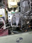
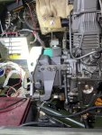
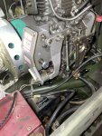
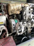
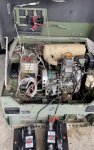
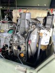
My MEP831a will not turn off . The shut off button will not stop her . I have to disconnect The battery for it to turn off . Other then that , no issues . Any suggestions.
Attachments
-
 95.6 KB Views: 36
 -
 102.6 KB Views: 34