It's very interesting. Thanks!
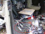
Looks like a very big 33V Zener diode, a thermal switch that closes when the chassis reaches a certain temperature, and an electronic temperature sensor that closes when the Zener diode reaches a certain temperature. There is a large 2-pole circuit breaker. The sensors trip the circuit breaker and remove power from the diode and the output when the temperature becomes excessive. I think the breaker has a high-current pole for the power through the unit, and a lower-current pole to be tripped by the temperature switch or sensor. (Mine is partly disassembled, will have to look later, maybe Bjorn may remember, since he has had them apart also.) The breaker poles are mechanically ganged so tripping one side trips the other. Unfortunately the part details are somewhat vague. - but this can definitely be repaired if broken, so that at least the spike/transient protection is retained.
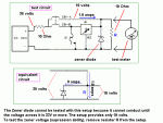
One thing I noticed in the -14 manual in the test section, figure 6-1 / table 6-3 is that they say to use two 10 ohm 10 watt resistors. One is in series with the power supply, and the other is across the output of the supressor.
The test is designed to determine if the Zener diode is able to limit the voltage to 33-36 volts.
I think the test procedure is mistaken and could present a small safety hazard. The resistor at the supresor output is going to get mighty hot if it has 33-36 volts across it.
-But assuming the power supply is set to 38V, the entire circuit as shown is essentially two 10 ohm resistors in series with the zener diode connected from the point in the center of the resistors to ground. With 38V across the resistor chain, the voltage across each resistor, and across the zener diode would be only 19 volts and it would not conduct. Each 10 ohm 10 watt resistor would have 19 volts across it and dissipate (19/10)*19, or 36.1 watts. (overload).
I believe the proper way to test it would be to not use the 10 ohm resistor shown at the output. Then, with 38 volts from the supply, the first 10 ohm resistor will limit the current to the zener diode because the zener diode will have enough voltage to conduct and the voltage would read the 33 to 36 volts.
I could be completely mistaken or mis-read the instructions, been wrong before, but to try to explain my point on the test, please see the schematic below. I'd welcome comments or corrections on this.


